
User manual

KeContact P20
Quick Installation Guide
Pay attention to the handling instructions, safety notes and
installation guidelines in the “KeContact P20 Installation manual”!
!
WARNING!
Not observing the safety instructions can result in risk of death,
injuries and damage to the device! KEBA AG assumes no liability for
claims resulting from this!
Electrical hazard!
The installation, commissioning and maintenance of the charging
station may only be performed by correctly trained, qualified and
authorized electricians who are fully responsible for the
compliance with existing standards and installation regulations.
Only connect voltages and circuits in the right-hand connection
area (Ethernet, terminals for control lines) that have a secure
separation to dangerous voltages (e.g. sufficient isolation).
1 / 2
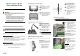
|1| Specifications for the electrical connection
The charging station is set to 10 amps in the delivery state.
Set the maximum EVSE current capacity by setting the DIP-switches in
coordination with your installed line circuit breaker (see chapter “DIP-switch
settings”).
The mains supply line must be hardwired to an existing house installation and
correspond to the nationally applicable legal conditions.
Selection of the RCD circuit breaker:
Each charging station must be connected to a separate RCD circuit breaker. No
other circuits may be connected to this RCD circuit breaker.
RCD circuit breaker of at least Type A.
In derogation with this, a RCD circuit breaker Type B can be a requirement by the
vehicle manufacturer. If the electric vehicles are not known (e.g., semi-public
area), the use of an RCD circuit breaker Type B is useful.
Dimensioning the Line circuit breaker:
Determine the nominal current in accordance with the specifications on the type
plate, in coordination with the desired charging current (DIP switch settings for the
pre-adjusted maximum EVSE current capacity) and the mains supply line.
I
DIPswitch
≤ I
Breaker
≤ I
Cable
≤ I
Rating
|2| Opening the connector panel
Cover screws
Unscrew the two cover screws
[S] on the bottom side of the
housing cover.
Remove the housing cover.
Removing the connector panel cover
Unscrew the four screws with
which the connector panel cover
is mounted and remove the
connector panel cover.
|3| Preparing the cable insertion
Breaking out the cable insertion
openings
Place the housing on a stable
support pad and use a hammer
and flathead screwdriver to
carefully break out the required
cable insertion openings.
Then insert the corresponding
feedthroughs (cable glands or
double-membrane seals)
Use the cable gland when
connecting from above!
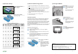
|4| Mounting the charging station
Mark and drill the four holes using the supplied drilling template and a spirit
level.
Water drainage
The water drainage from the top side to
the rear side of the charging station must
be ensured. Therefore, observe the
following:
Only a vertical installation of the
charging station is permitted.
The charging station must be
mounted at an angle of 90° (no
inclination is permitted!).
Mounting the charging station
Turn the hanger bolts into the
anchors until the thread still
protrudes approx. 2 cm ('x').
Use the shims [A] to compensate
for any unevenness and to
ensure a water drainage behind
the device.
Position and mount the charging
station using the supplied
washers and nuts.
[A]…shim
[B]…charging station housing
[C]…washer
[D]…nut
|5| Electrical connection
The cable sheathing must reach into the housing.
Connecting the mains supply line
Shorten the connection wires to
the appropriate length; these
should be kept as short as
possible.
The PE conductor must be longer
than the remaining conductors!
Strip approx.12 mm from the
connection wires.
Wire end sleeves are
recommended for finely stranded
wires.
Perform the connection of the
mains supply line [L1], [L2], [L3],
[N] and [PE].
1-phase connection
It is also possible to perform a 1-phase
connection of the charging station. Use
the terminals [L1],[N] and [PE].
Supply terminals
The supply terminals are designed as
spring-type terminals.
Insert the flathead screwdriver
(blade with 5.5 mm) into the
supply terminal as shown on the
picture.
Terminal data:
- inflexible (min.-max): 0.2 – 16 mm²
- flexible (min.-max): 0.2 – 16 mm²
- AWG (min.-max): 24 – 6
- flexible (min.-max) with wire end
sleeve:
Without/with plastic sleeve
0.25 – 10 / 0.25 – 10 mm²
- Stripping length: 12 mm
- Flathead screwdriver: 5.5 mm