
Installation & Maintenance Manual Owner's manual

– 10 –
The appliance must be isolated from the gas supply
piping system by closing its individual manual shutoff
valve during any pressure testing of the gas supply
piping system at test pressure equal to or less than
1/2 psig (3.5 kPa).
For additional piping information, refer to National Fuel
Gas Code ANSI Z233.1-1999, or latest edition.
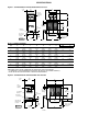
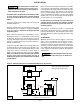
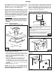
Figure 9a - Drip Leg Installation
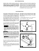
Figure 9b - Field Piping Recommendations
DUCT SPECIFICATIONS
Ductwork connected to duct furnaces should have
removable access panels on both the upstream and
downstream sides of the unit. These openings should be
accessible when the unit is installed, and should be
sized so that smoke or reflected light can be observed
inside the casing to indicate the presence of leaks in the
heating equipment. The covers of the openings should
be attached in a manner that prevents leaks.
Ductwork which is outdoors must be insulated and
sealed to prevent water from entering either furnace or
building through the duct. Do not alter the flange
connection for the duct attachment; air may bypass
and cause combustion problems. Be sure to properly
seal to avoid any air leakage (refer to Figures 1 and 2).
GAS CONNECTIONS
All gas piping should be installed in accordance with
local codes. It is required that a ground union be
installed adjacent to the manifold for easy servicing. On
vertical runs, a drip leg should be provided upstream of
the control manifold (see figure 9a). An additional shut-
off must be located externally of the jacket enclosure
where required by local code. The location of this valve
must comply with the local codes. A 1/8-inch N.P.T.
plugged tapping, accessible for test gauge connection,
must be installed immediately upstream of the gas
supply connection to the unit. Field gas piping
recommendations are shown in Figure 9b.
It is recommended that the gas piping not be installed
through the bottom of the duct furnace bottom panel. If
piping must penetrate the duct furnace bottom panel, it
must be sealed to prevent water leakage.
To avoid equipment damage or
possible personal injury, do not connect gas
piping to this unit until a supply line pressure/leak
test has been completed. Connecting the unit
before completing the pressure/leak test may
damage the unit gas valve and result in a fire
hazard.
Do not rely on a shutoff valve to
isolate the unit while conducting gas pressure/leak
tests. These valves may not be completely shut off,
exposing the unit gas valve to excessive pressure
and damage. Do not overtighten the inlet gas piping.
This may cause stresses that would crack the valve.
Never use an open flame to detect
gas leaks. Explosive conditions may exist which
would result in personal injury or death.
The gas line should be supported so that no strain is
The gas line should be supported so that no strain is
placed on the unit. Pipe compounds which are not
soluble to liquid petroleum gases should be used on
threaded joints.
The appliance and its individual shutoff valve must be
disconnected from the gas supply piping system during
any pressure testing of that system at test pressure in
excess of 1/2 psig (3.5 kPa).
3 In. (Min.)
76mm. (Min)
TO GAS CONTROLS
TO GAS LINE
ALTERNATE TO
GAS LINE
DRIP LEG
D3587
D3587
UNION
NIPPLE
NIPPLE
ELBOW
ELBOW
NIPPLE
UNION
NIPPLE
D3726
D3726