
Installation & Maintenance Manual Owner's manual


– 12 –
Nominal
Iron
Pipe Size
Internal
Dia.
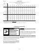
Maximum Capacity of Pipe in Cubic Feet of Gas per Hour for Gas Pressures of 0.5 psig (3.5 kPa) or Less,
and a Pressure Drop of 0.5 Inch Water Column (124.4 Pa)
(Based on a 0.60 Specific Gravity Gas)
Length of Pipe, ft. (Meters)
GAS PIPE SIZE
in. in. 10 20 30 40 50 60 70 80 90 100 125 150 175 200
(mm) (3.0) (6.1) (9.1) (12.2) (15.2) (18.3) (21.3) (24.4) (27.4) (30.5) (38.1) (45.7) (53.3) (61.0)
1/2 0.622 175 120 97 82 73 66 61 57 53 50 44 40 37 35
(16) (4.96) (3.40) (2.75) (2.32) (2.07) (1.87) (1.73) (1.61) (1.50) (1.42) (1.25) (1.13) (1.05) (0.99)
3/4 0.824 360 250 200 170 151 138 125 118 110 103 93 84 77 72
(21) (10.2) (7.08) (5.66) (4.81) (4.28) (3.91) (3.54) (3.34) (3.11) (2.92) (2.63) (2.38) (2.18) (2.04)
1 1.049 680 465 375 320 285 260 240 220 205 195 175 160 145 135
(27) (19.3) (13.2) (10.6) (9.06) (8.07) (7.36) (6.80) (6.23) (5.80) (5.52) (4.96) (4.53) (4.11) (3.82)
1 1/4 1.380 1400 950 770 660 580 530 490 460 430 400 360 325 300 280
(35) (39.6) (26.9) (21.8) (18.7) (16.4) (15.0) (13.9) (13.0) (12.2) (11.3) (10.2) (9.20) (8.50) (7.93)
1 1/2 1.610 2100 1460 1180 990 900 810 750 690 650 620 550 500 460 430
(41) (59.5) (41.3) (33.4) (28.0) (25.5) (22.9) (21.2) (19.5) (18.4) (17.6) (15.6) (14.2) (13.0) (12.2)
2 2.067 3950 2750 2200 1900 1680 1520 1400 1300 1220 1150 1020 950 850 800
(53) (112) (77.9) (62.3) (53.8) (47.6) (43.0) (39.6) (36.8) (34.5) (32.6) (28.9) (26.9) (24.1) (22.7)
2 1/2 2.469 6300 4350 3520 3000 2650 2400 2250 2050 1950 1850 1650 1500 1370 1280
(63) (178) (123) (99.7) (85.0) (75.0) (68.0) (63.7) (58.0) (55.2) (52.4) (46.7) (42.5) (38.8) (36.2)
3 3.068 11000 7700 6250 5300 4750 4300 3900 3700 3450 3250 2950 2650 2450 2280
(78) (311) (218) (177) (150) (135) (122) (110) (105) (97.7) (92.0) (83.5) (75.0) (69.4) (64.6)
4 4.026 23000 15800 12800 10900 9700 8800 8100 7500 7200 6700 6000 5500 5000 4600
(102) (651) (447) (362) (309) (275) (249) (229) (212) (204) (190) (170) (156) (142) (130)
Chart 3
1. *See local codes before installing 1/2" pipe.
Input Rate of Unit
2. FOR NATURAL GAS: cu. ft./hr. =
Btu Value of Gas
3. FOR PROPANE GAS: Multiply the Cu. Ft. / Hr. obtained in note 2 by 0.633 before entering chart.
ELECTRICAL CONNECTIONS
HAZARDOUS VOLTAGE!
DISCONNECT ALL ELECTRIC
POWER INCLUDING REMOTE
DISCONNECTS BEFORE
SERVICING. Failure to
disconnect power before
servicing can cause severe
personal injury or death.
The rooftop duct furnace is wired at the factory and
ready to be connected. Actual wiring will differ
according to the options used. Each furnace will be
shipped with its own wiring diagram; refer to this wiring
diagram for all electrical connections to the unit.
All electrical connections must conform to: ANSI/NFPA
No. 70-1999 (or latest edition) National Electrical Code
and applicable local codes; In Canada, to the Canadian
Electrical Code, Part I CSA Standard C22.1.
Do not use any tools (i.e. screwdriver,
pliers, etc.) across the terminals to check for power.
Use a voltmeter.
The outdoor conduits leading into the unit should be
installed to prevent rain from wetting any high voltage
wire. Locate the thermostat in accordance with the
instructions packed with each thermostat.
NOTICE: Should any original wire supplied with the
heater have to be replaced, it must be replaced with
wiring material having a temperature rating of at least
105°C (221°F).