
Installation & Maintenance Manual Owner's manual


– 15 –
GAS CONTROLS continued
TWO-STAGE CONTROL
Optional two-stage control is provided with a two-stage
gas valve capable of firing at 100% and 40% of rated
input. Ignition at a low fire (40% of the unit's rated input)
and the unit is typically controlled by a voltage two-stage
thermostat.
With power applied to the unit, this system operates in
the following manner:
1. The first stage of the thermostat call for heat.
2. The pilot valve opens.
3. The ignitor sparks continuously to ignite the pilot.
4. The sensor proves pilot ignition and shuts off the
ignitor.
5. With the pilot lit, the main gas valve open to low fire.
6. Main burners are lit at 40 percent of unit's rated
input.
7. The fan time delay relay (optional) allows the heat
exchanger to come up to operating temperature. At
this time, the fan time delay closes and activates the
fan motor.
8. If additional heat is required, the second stage of the
thermostat calls for heat.
9. The main gas valve opens to full fire. The main
burners are now at full fire. The unit continues a full
fire until the second stage of the thermostat is
satisfied and no longer call for heat.
10. The main valve closes to low fire. The main burners
are now at low fire. The unit continues at low fire until
the first stage of the thermostat is satisfied and no
longer calls for heat.
11. The main and pilot valves closes.
12. The fan time delay remains closed, keeping the
fan operating to dissipate residual heat from the
heat exchanger. At this time, the fan time delay
relay opens and deactivates the fan motor.
HYDRAULIC MODULATING CONTROL
Natural gas or propane units with hydraulic modulating
control are provided with a modulating gas valve
capable of firing from 40 percent to 100 percent of rated
input. Ignition is at low fire (40 percent of input). The
hydraulic modulating valve is controlled by a sensing
bulb located in the discharge air stream which
modulates the gas input from 40 percent to 100 percent
of rated input. The modulating valves are available in
two temperature ranges: 60-100°F or 75-200°F; setpoint
adjustments (± 3-5°) are shown in the following table:
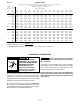
Dial Setpoint 123456789
60-100°F 6065707580859095100
75-200°F 75 91 106 122 138 150 NA NA NA
NA = Maximum furnace discharge temperature allowed = 150°F.
The unit is also provided with an automatic electric valve
in series with the hydraulic modulating valve, which
typically cycles the unit in response to a low voltage
single-stage thermostat. Units not utilizing a thermostat
will operate as a standing pilot unit. The ignitor will light
the pilot and the pilot will remain on until power is
disconnected from the units.
With power applied to the unit, this system operates in
the following manner:
1. The thermostat calls for heat.
NOTICE: If a thermostat is not supplied, steps 2
through 5 will be constant as long as power is applied
to the unit.
2. The pilot valve opens.
3. The ignitor sparks continuously to ignite the pilot.
4. The sensor proves ignition and shuts off the ignitor.
5. With the pilot lit, the main electric gas valve opens.
At this time, the fan time delay (optional on duct
furnaces) is energized. The fan time delay relay
closes and activates the fan motor.
NOTICE: The unit firing rate is controlled by the
hydraulic sensing bulb on the mechanical valve is in
series with the single-stage electrically operated
valve.
6. The Hydraulic sensing bulb, on the mechanical
modulating valve, calls for heat.
7. The mechanical modulating valve opens allowing
gas flow to the main burners. Main burners are lit at
40 percent of the unit's rated input. The mechanical
modulating valve modulates between 40 percent
and 100 percent of firing rate depending on the
temperature rise required.
8. The unit continues to fire until the hydraulic sensing
bulb is satisfied and no longer calls for heat.
9. The mechanical modulating valve closes which
shuts off the main gas supply to the burners.
10. The room thermostat is satisfied and no longer calls
for heat. The main and pilot valves close. At this time
the fan delay relay opens and deactivates the fan
motor.
HYDRAULIC MODULATING CONTROL
WITH BYPASS
Natural or propane gas units only with an additional
electric valve are provided in parallel with the hydraulic
modulating valve. The electric valve bypasses the gas
flow around the hydraulic modulating valve's sensing
bulb control. The electric valve is activated by a low
voltage single-stage thermostat.