
Installation & Maintenance Manual Owner's manual


– 18 –
LIGHTING continued
2. Turn on electrical power. The unit should now be
under the control of the thermostat.
3. Turn the thermostat to the high heat reading to see
if the pilot and main burner ignite.
4. Turn the thermostat to the lowest setting to
interrupt power to the ignition system to determine
that both the pilot burner and main burner are
extinguished.
5. Set the thermostat at the desired setting for normal
operation.
For complete shutdown:
1. Turn the main and pilot valves to the OFF
position.
2. Shut off electric power.
3. Adjust the thermostat to the lowest setting.
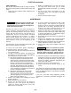
Figure 12 - Main Burner Flames
NOTICE: There may be momentary and spasmodic
orange flashes in the flame. This is caused by the
burning of airborne dust particles, and not to be
confused with the yellow tipping, which is a stable
or permanent situation when there is insufficient
primary air.
1. With unit firing, remove the pilot adjustment cap.
2. Adjust the pilot screw to provide properly sized
flame.
PILOT ADJUSTMENT
3. A proper pilot flame is a soft steady flame that
envelopes 3/8 to 1/2 inch (9.5 to 12.7 mm) of the
flame sensor.
4. Replace the pilot adjustment cap.
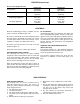
* This schedule is for units operating within the U.S.A.
at normal altitudes of 2000 ft. (610m) or less. For
altitudes above 2,000 ft., refer to local codes, or in
absence of local codes, refer to the National Fuel Gas
Code ANSI Standard Z223-1999 (N.F.P.A. no. 54) or
the latest edition.
When installed in Canada, any references to deration
at altitudes in excess of 2000 feet (610m) are to be
ignored. At altitudes of 2000 to 4500 feet (610 to
1372m), the unit heaters must be orificed to 90% of the
normal altitude rating, and be so marked in accordance
with the CSA certification.
*
INPUT
IN
1000
BTU
2500 BTU/Ft
3
(93.1 MJ/m
3
)
PROPANETYPE OF GAS NATURAL
HEATING VALUE
1075 BTU/Ft
3
(40.1 MJ/m
3
)
3.5" W.C.
(0.87kPA)
10" W.C.
(2.49 kPA)
NO. OF
BURNER
ORIFICES
MANIFOLD
PRESSURE
96
42
120
42
140
42
163
42
186
42
210
42
233
42
280
42
326
42
372
42
40
54
50
54
60
54
70
54
80
54
90
54
100
54
120
54
140
54
160
54
100
125
150
175
200
225
250
300
350
400
4
5
6
7
8
9
10
12
14
16
FT
3
/HR
ORIFICE DRILL
FT
3
/HR
ORIFICE DRILL
FT
3
/HR
ORIFICE DRILL
FT
3
/HR
ORIFICE DRILL
FT
3
/HR
ORIFICE DRILL
FT
3
/HR
ORIFICE DRILL
FT
3
/HR
ORIFICE DRILL
FT
3
/HR
ORIFICE DRILL
FT
3
/HR
ORIFICE DRILL
FT
3
/HR
ORIFICE DRILL
For correct air adjustment, close the air shutter until
yellow tips in the flame appear. Then open the air
shutter to the point just beyond the position where
yellow tipping disappears.
PRIMARY AIR SHUTTER ADJUSTMENT
After the unit has been operated for at least 15
minutes, adjust the primary air flow to the burners. Turn
the friction-locked, manually-rotated air shutters
clockwise to close, or counterclockwise to open.
Chart 5 - Main Burner Orifice Schedule*
D3652
NORMAL
(
HARD FLAME
)
YELLOW TIPPING
(MARGINAL)
YELLOW FLAME
(TOO LITTLE AIR)
LIFTING
(TOO MUCH AIR)