
Installation & Maintenance Manual Owner's manual

– 2 –
TABLE OF CONTENTS
RECEIVING/PRE-INSTALLATION
INSTRUCTIONS .................................................... 2
GENERAL SAFETY INFORMATION .................. 2, 3
SPECIFICATIONS
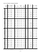
Dimensional Data ........................................ 4, 5
Performance and Specification Data ............... 5
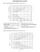
Performance Data Curves ........................... 6, 7
INSTALLATION
Location/Mounting ................................... 2, 3, 8
Clearances ............................................... 4, 5, 8
Venting ............................................................. 9
Duct and Drain Specifications ........................ 10
Gas Connections ............................... 10, 11, 12
Electrical Connections ................................... 12
OPERATION
General Information ................................. 13, 14
Auto Spark Parts ............................................ 13
Controls ......................................................... 14
Gas Controls ...................................... 14, 15, 16
Air Distribution/Throughput ............................ 17
Lighting .................................................... 17, 18
Primary air Shutter/Pilot Adjustment .............. 18
Gas Input Adjustment .................................... 19
START-UP ...................................................... 19, 20
MAINTENANCE .............................................. 20, 21
TROUBLE SHOOTING GUIDE........................ 22-25
REPLACEMENT PARTS ...................................... 26
WARRANTY.......................................................... 26
GAS EQUIPMENT CHECK SHEET...................... 27
The following terms are used throughout this manual to
bring attention to the presence of potential hazards or to
important information concerning the product:
Indicates an imminently hazard-
ous situation which, if not avoided, will result in
death, serious injury or substantial property
damage.
Indicates an imminently hazard-
ous situation which, if not avoided, could result
in death, serious injury or substantial property
damage.
Indicates an imminently hazardous
situation which, if not avoided, may result in minor
injury or property damage.
NOTICE: Used to notify of special instructions on
installation, operation or maintenance which are
important to equipment but not related to personal
injury hazards.
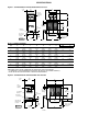
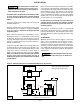
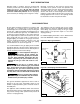
SERVICE ACCESS PANEL REMOVAL
To remove an access panel door, use the following
procedure: remove the two screws and two washers
from the louvered flue discharge area of the service
panel (power vent doors only). Each panel is held in
place with two “Grip” Latches. Using a slotted head
screw driver, turn the latch screwhead counter
clockwise. Using the handle provided, pull the panel
upwards. Pull the bottom of the panel out and lower the
panel to disengage it from the top lip. To replace an
access door panel, guide the panel door upwards on the
tracks, and push up into the top lip; swing and lower the
panel in place until it engages with the bottom panel.
Turn the screwhead on each latch clockwise. The screw
must turn freely one quarter turn before resistance is felt
in order for the lock to engage. If the latch does not hold,
turn the screw counter-clockwise several turns and
repeat the above procedure. Also refer to Figures 8Aa,
8b and 8c. for more specifications.
RECEIVING INSTRUCTIONS
Inspect shipment immediately when received to
determine if any damage has occurred to the
carton/crate during shipment.
After the unit has been uncrated, check for any visible
damage to the unit. On power vented units, check
motor position and turn blower wheel by hand to
determine if damage has occurred to these critical
parts.
If any damage is found, the consignee should sign the
bill of lading indicating such damage and immediately
file claim for damage with the transportation company.
PRE-INSTALLATION INSTRUCTIONS
When unit is received and uncrated check data plate
on unit for type of gas and electrical specifications and
make certain that these agree with those at point of
installation.
Open all disconnect switches
and secure in that position before installing the
unit. Failure to do so may result in personal
injury or death from electrical shock.
NOTICE: It is the equipment owner’s responsibility
to provide any scaffolding or other apparatus
required to perform emergency service or annual/
periodic maintenance to this equipment.
RIGGING
Rig the unit using either belt or cable slings. Use
spreader to protect the top of the unit when it is lifted.
The furnace units are provided with two holes in the
base rail on each side of the unit. Slide pipes beneath
the unit through these holes and attach rigging to the
pipes for lifting the unit.
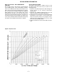
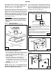
LOCATION
Before placing the rooftop unit in its permanent
location, make certain that the roof is capable of
carrying the additional load of this equipment. Check
the shipping weights given in Chart 2.
Refer to Figures 1, 2 and 6 and charts 1 and 2 for
adequate unit dimensions and required clearances.
MOUNTING
The units are mounted on skids and are suitable for
use on combustible flooring. It is recommended that the
skids be mounted either on level solid planking or steel
channels, but never on a soft tar roof where the skids
could sink and reduce the clearance between the
bottom panel and the roof.