
Installation & Maintenance Manual Owner's manual

– 3 –
GENERAL SAFETY INFORMATION
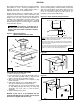
vent through a protective grille, and the design of the
vent cap is such that the products of combustion are
discharged at the upper section of the cap. This cap is
shipped in a separate carton. It should be fastened in
position as shown in Figure 7 and should not be
altered in any way.
The Power Vented unit has a power venting system
with the inlet and discharge grille located in the upper
section of the side access panel. This balanced flue
design also performs well under all wind conditions.
All internal parts of the standard unit are fabricated
from aluminized steel. Standard burners are pressed
aluminized steel and have a stainless steel burner port
protector and air shutters. All internal and external
jacket parts are fabricated from galvanized steel.
Stainless steel heat exchangers, burners and flue
collectors are optional. An optional 321 or 409 stainless
steel heat exchanger is highly recommended for the
following applications:
1) When the entering air temperature is below
40°F (4.4°C).
2) When the furnace is installed downstream of a
cooling coil section.
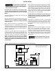
A pilot burner plate is provided for access to the pilot
burner and ignition systems without removing the
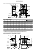
burner drawer. Clearances between the external unit
and obstruction must be sufficient for proper servicing
of pull-out drawer. See Figures 1 and 2 for this
clearance.
The outdoor units are certified for operation on either
natural or propane gas. If a unit is to be installed at an
altitude exceeding 2000 ft. (610 m) above sea level,
derate the input by 4% for each 1000 foot rise (305 m
rise) above sea level. Check all local codes.
Special orifices are required for installations above
2000 ft. (610 m). Check all local codes.
In Canada, if a unit is to be installed at altitudes of
2000 ft. (610 m) to 4500 ft. (1372 m), the unit must be
orificed to 90% of the normal altitude rating.
Unless otherwise specified, the following conversions
may be used for calculating SI unit measurements:
1 inch = 25.4 mm
1 foot = 0.305 m
1 gallon = 3.785 L
1 pound = 0.435 kg
1 psig = 6.894 kPa
1 cubic foot = 0.028 m
3
Roofcurb kits for rooftop gas heating units are shipped
knocked down. A curb kit contains (insulated) curb
rails, hardware, sealant, self-adhering rubber
gasketing, and installation instructions. Roof insulation,
cant strips, flashing, roof felts, caulking and nails must
be furnished by the installer. See separate curb
specifications from manufacturer.
Failure to comply with the
general safety information may result in
extensive property damage, severe personal
injury or death!
Do not alter the unit heater in
any way or damage to the unit and/or severe
personal injury or death may occur!
Never service any component
without first disconnecting all electrical and
gas supplies to the unit or severe personal
injury or death may occur!
Ensure that all power sources
conform to the requirements of the unit heater or
damage to the unit will result!
Installation must be made in accordance with local
codes, or in absence of local codes, with ANSI
Standard Z223.1-1999 (N.F.P.A. No. 54) National Fuel
Gas Code, or the latest edition. All of the ANSI and
NFPA Standards referred to in these installation
instructions are those that were applicable at the time
the design of the appliance was certified. The ANSI
Standards are available from the American Gas
Association, 1515 Wilson Boulevard, Arlington, Virginia
22209. The NFPA Standards are available from the
National Fire Protection Association, Batterymarch
Park, Quincy, MA 02269.
If installed in Canada, the installation must conform
with local building codes, or in absence of local building
codes, with current CGA-B149.1 “Installation Codes for
Natural Gas Burning Appliances and Equipment” or
CGA-B149.2 “Installation Codes for Propane Gas
Burning Appliances and Equipment”. These outdoor
duct furnaces have been designed for and certified to
comply with CGA 2.8.
These units have been designed and certified for
outdoor use only, and may be located on the roof of the
building or at any convenient location external of the
building to be heated. The input range is 100,000 BTU/
HR. (29.3 kW) to 400,000 BTU/HR. (117.1 kW) in 50,000
BTU/HR. (14.6 kW) increments.
The venting is an integral part of the unit and must not
be altered in the field. The Natural Vented units are
equipped with a vent cap which is designed for gravity
venting. Air for combustion enters at the base of the
1000 Btu/Cu. Ft. = 37.5 MJ/m
3
1000 Btu per hour = 0.293 kW
1 inch water column = 0.249 kPa
liter/second = CFM x 0.472
meter/second = FPM ÷ 196.8