
Installation & Maintenance Manual Owner's manual

– 9 –
D4596
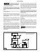
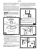
Power vented models are designed with combustion
air inlet and flue products outlet located in the louvered
side access panel. Never locate these units in an area
where the flue products outlet may be directed at any
fresh air vents.See Figures 8a 8b, and 8c for
installation and servicing requirements.
Figure 8a - Power Venter Discharge Location
Figure 8b
Figure 8c
VENTING
All venting installations shall be in accordance with the
latest edition of “Part 7, Venting of Equipment of the
National Fuel Gas Code, ANSI Z223.1-1999, or
applicable provisions of local building codes”.
Natural venting models are equipped with a vent cap
designed for natural venting. Air for combustion enters
at the base of the vent through a protective grille, and the
design of the vent cap is such that the products of
combustion are discharged at the upper section of the
cap. The cap is shipped in a separate carton. It should
be fastened in position as shown in Figure 7 and should
not be altered in any way.
The venting is an integral part of
the unit and must not be altered in the field. If
altered, excessive carbon monoxide could be
produced.
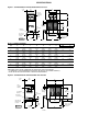
Figure 7 - Vent Cap Assembly
(Natural Vented Furnaces Only)
FIELD INSTALLATION INSTRUCTIONS
1. Remove “Side Access Panel”.
2. Insert Vent Sleeve of “Vent Cap Assembly” (Item 1)
thru “Top Panel Assembly” (Item 2), and over Vent
Collar of “Flue Collector Assembly” (Item 3).
3. Align “Vent Cap Assembly” so it is square to “Top
Panel Assembly”.
4. Fasten with “Drill Screw” or “Sheet Metal Screw”
(Item 4) by reaching between “Flue Collector
Assembly” (Item 3) & “Top Panel Assembly” (Item
2), and drilling through vent sleeve of “Vent Cap
Assembly” into vent collar of “Flue Collector
Assembly”.
5. Replace “Side Access Panel”.
NOTICE: If your unit is to be equipped with the
optional extended vent cap assembly, see the special
instructions supplied with the vent cap.
D3591
2
1
4
3
FRONT
REAR
LEFT
RIGHT
D
3591
D4596
*These Surfaces (indicated with an asterisk in figures 8a & 8b)
MUST be flush and sealed at all times to ensure the proper
discharge of flue products from the unit.
These discharge flanges are equipped with special gasketing,
which must create an air tight seal connection around the louvers
of the access panel.
Secure in place the access door to the discharge adaptor using the
two screws and neoprene washers, then tighten the grip
latches (see service access panel removal section).
D3505
TOP VIEW
Neoprene Washers
Screws
D3725