
User manual


Appendix
C: Communication interface Model 2110 5½ Digit Multimeter Refere
nce Manual
C-6 2110-901-01 Rev. C/August 2013
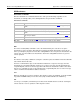
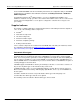
Figure 48: USB connector
Contact number Signal name Typical wiring assignment Description
1
VBUS
Red
Floating
2
D-
White
Limit Test Pass
3
D+
Green
Limit Test Fail
5
GND
Black
GND
If you turn off the USB interface, the Pass/Fail output function will turn on automatically.
If you want to use the Pass/Fail signal output, you must use the GPIB interface for remote control.
Disconnect the USB cable from your instrument while using the Pass/Fail signal output.
To turn on and off the pass/fail output:
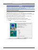
1. Press the SHIFT key, and then press the CONFIG key.
2. Use the ► and ◄ keys to select INTERFACE.
3. Press ENTER.
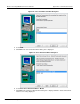
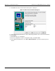
4. Use the ► and ◄ keys to:
• Select GPIB to turn on the output.
• Select USB to turn off the output.
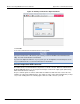
5. Press ENTER.