
User manual


Series 3700 System Switch/Multimeter Reference Manual Section 14: Verification
3700S-901-01 Rev. C / July 2008 14-11
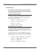
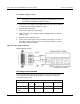
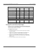
Connect to the Fluke 5700A calibrator
Description
Range (V)
Test point
(V)
Lower limit (V)
Upper limit (V)
Verify ACV 10V @ 100kHz
1.00E+01
1.00E+01
9.932000E+00
1.006800E+01
Verify ACV 100V @ 1kHz
1.00E+02
1.00E+02
9.992000E+01
1.000800E+02
Verify ACV 100V @ 50kHz
1.00E+02
1.00E+02
9.984000E+01
1.001600E+02
Verify ACV 100V @ 100kHz
1.00E+02
1.00E+02
9.932000E+01
1.006800E+02
Verify ACV 300V @ 1kHz
3.00E+02
3.00E+02
2.997600E+02
3.002400E+02
Verify ACV 300V @ 50kHz
3.00E+02
3.00E+02
2.995200E+02
3.004800E+02
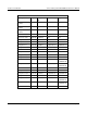
Connect to the Fluke 5725A amplifier
Description
Range (V)
Test point
(V)
Lower limit (V)
Upper limit (V)
Verify ACV 300V @ 100kHz
3.00E+02
3.00E+02
2.979600E+02
3.020400E+02
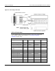
Verifying DC current 10µA to 100µA ranges
Check DC current accuracy by applying accurate current from the DC current
calibrator to the Series 3700 analog backplane connector and verifying that the
displayed readings fall within specified limits.
To verify DC current accuracy:
1. Set up the Series 3700 for DC current and the range being tested. Make
sure REL is disabled.
2. Verify the zero test point for each range without any connection to the
equipment and verify that the readings fall within specified limits.
3. Connect the Series 3700 AMPS and LO INPUT pins to the DC current
calibrator as shown in the "DC current verification 10uA to 100uA ranges
diagram" below.
4. Set up the HP3458A to the DC current function and range.