
Installation Guide


MONITOR ARM
16 The Monitor Arm is positioned by means of a channel above the glands at the
rear of the casting, and is secured by a clamp with two retaining screws. The
neon points to starboard when viewed from the rear of the transceiver.
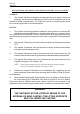
17 The cable is routed through the gland nearest the channel and connects to PLA-7
(red) and PLA-8 (blue) on the Azimuth PCB (CTX-A106). Refer to Figure 3.
ELECTRICAL CONNECTION
18 For detailed electrical connection of cables to the transceiver unit, refer to the
installation diagrams in Figure 5. Figure 7 shows a typical arrangement with the
MkIV transceiver connected to the NUCLEUS 3 Display, via the Radar Interface Unit
(RIU). Ensure that all cables are secured to their associated entry point and that
screened cables are earthed to their respective units.
19 Connecting cables between the display and the transceiver should be limited to a
length of 65 metres. Where the distance between transceiver and display
exceeds 65 metres, special low loss co-axial cable should be used. Where the distance
between transceiver and display exceeds 180 metres, special low loss co-axial cable,
and line amplifiers for video and sync must be fitted (see Annex A).
20 Cable specifications are detailed in Paragraphs 24 onwards.
CHECKS AFTER FITTING
21 Setting to work instructions are described in Chapter 3, Commissioning. The
transceiver must be thoroughly checked for security, accessibility, and correct
cabling runs.
mkiv 7 Issue 1
KH1254
Chapter 2
TO TX MONITOR ARM
CAE-A106
RED
PLA
BLUE
6
12345678910
CD-1134
Figure 3 - X-Band Upmast Transceiver Transmitter Monitor Arm:
Connection Diagram