SBS-800 SERIES SHORE BASED RADAR SYSTEMS OPERATOR & PLANNED MAINTENANCE HANDBOOK FIBRE SHARPEYE™ TRANSCEIVER SYSTEMS KH-1601-2 Issue 6
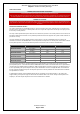
SBS-800 Series Installation and Termination Handbook DOCUMENT HISTORY Issue number Release date 1 April 2013 2 October 2015 3 November 2016 4 February 2017 Details First release Updates to the handbook layout General corrections Addition of data for the SBS-800-3 system Handbook format revised. X-Band SharpEye™ details updated from GaAs to GaN. S-Band fibre SharpEye™ details added. RadHaz figures updated (see health & safety section).
SBS-800 Series Operator & Planned Maintenance Handbook Chapter 1: Contents 1 Contents 1 Contents ..................................................................................................................................... 3 2 Health and Safety Warnings..................................................................................................... 5 2.1 2.2 3 English Health and Safety Warnings ......................................................................................
SBS-800 Series Operator & Planned Maintenance Handbook Chapter 1: Contents 8.3 9 External Commands .............................................................................................................. 59 Planned Maintenance ............................................................................................................. 61 9.1 9.2 9.3 9.4 Overview and Safety Notices ................................................................................................
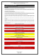
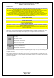
SBS-800 Series Operator & Planned Maintenance Handbook Chapter 2: Health and Safety Warnings 2 Health and Safety Warnings 2.1 English Health and Safety Warnings FCC NOTICES IC RSS-GEN, Sec 8.4 Warning Statement- (Required for license-exempt devices) This device complies with Industry Canada license-exempt RSS standard(s).
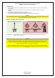
SBS-800 Series Operator & Planned Maintenance Handbook Chapter 2: Health and Safety Warnings RADIATION HAZARDS WARNING: RADIATION HAZARD- NON-IONISING Avoid exposure to the main beam of a stationary radar antenna. Avoid standing closer than 2 metres from the central front face of the antenna. Users of cardiac pacemakers should be aware of the possibility that radio frequency transmissions can damage some devices or cause irregularities in their operation.
SBS-800 Series Operator & Planned Maintenance Handbook Chapter 2: Health and Safety Warnings WORKING ALOFT CAUTION: SAFETY ALOFT When working aloft or near any radar scanners, moving or RF radiating equipment, ALL power sources to the platform and equipment including Anti-Condensation Heater (ACH) supplies must be fully isolated. Prior to working aloft, all AC supply breakers to the system must be switched OFF and locked.
SBS-800 Series Operator & Planned Maintenance Handbook Chapter 2: Health and Safety Warnings ANTI-STATIC HANDLING HANDLING OF ELECTROSTATIC-SENSITIVE SEMICONDUCTOR DEVICES Certain semiconductor devices used in the equipment are liable to damage due to static voltage.
SBS-800 Series Operator & Planned Maintenance Handbook Chapter 2: Health and Safety Warnings SOFTWARE LICENSING Only approved software may be used on Kelvin Hughes equipment. The use of unapproved or unlicensed software on any Kelvin Hughes equipment is strictly prohibited. The use of such software voids the warranty status of the unit.
SBS-800 Series Operator & Planned Maintenance Handbook Chapter 2: Health and Safety Warnings ANTENNA LIFTING Care should be taken when unpacking or lifting antennas to ensure that the waveguide is not bent, crushed or damaged during handling. Support the antenna near the ends when lifting it out of the packing and when fitting into position on the turning mechanism. Do not lift, handle or support the antenna by the waveguide. When rotating an installed antenna by hand, do not apply excessive force.
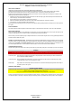
SBS-800 Series Operator & Planned Maintenance Handbook Chapter 2: Health and Safety Warnings 2.2 Recommandations sanitaires et de sécurité FCC STATEMENT IC RSS-GEN, Sec 8.4 Warning Statement- (Required for license-exempt devices) Le présent appareil est conforme aux CNR d'Industrie Canada applicables aux appareils radio exempts de licence.
SBS-800 Series Operator & Planned Maintenance Handbook Chapter 2: Health and Safety Warnings RISQUES D’IRRADIATION AVERTISSEMENT: RISQUE D’IRRADIATION NON-IONISANTE Évitez l’exposition au faisceau principal d’une antenne radar stationnaire. Évitez de vous tenir à moins de 2 mètres de la face avant centrale d’une antenne rayonnant.
SBS-800 Series Operator & Planned Maintenance Handbook Chapter 2: Health and Safety Warnings TRAVAIL DANS LA MÂTURE ATTENTION : LA SÉCURITÉ EN ALTITUDE Lorsque vous travaillez en hauteur ou à proximité d'un scanner radar, d'un équipement mobile ou d'un équipement émettant des radiofréquences, TOUTES les sources d'alimentation de la plate-forme et de l'équipement, y compris le chauffage anticondensation (ACH), doivent être totalement isolées.
SBS-800 Series Operator & Planned Maintenance Handbook Chapter 2: Health and Safety Warnings TRAITEMENT ANTISTATIQUE LA MANIPULATION DE DISPOSITIFS SEMI-CONDUCTEURS SENSIBLES À L'ÉLECTROSTATIQUE Certains dispositifs à semi-conducteurs utilisés dans l'équipement sont susceptibles d'être endommagés par la tension statique.
SBS-800 Series Operator & Planned Maintenance Handbook Chapter 2: Health and Safety Warnings LICENCES DE LOGICIELS Seuls les logiciels approuvés peuvent être utilisés sur les équipements HENSOLDT. L'utilisation de logiciels non approuvés ou sans licence sur tout équipement HENSOLDT est strictement interdite. L'utilisation d'un tel logiciel annule le statut de garantie de l'appareil.
SBS-800 Series Operator & Planned Maintenance Handbook Chapter 2: Health and Safety Warnings LEVAGE D'ANTENNE Lors du déballage ou du levage des antennes, il convient de veiller à ce que le guide d'ondes ne soit pas plié, écrasé ou endommagé pendant la manipulation. Soutenez l'antenne près des extrémités lorsque vous la sortez de l'emballage et que vous la mettez en place sur le mécanisme de rotation. Ne pas soulever, manipuler ou soutenir l'antenne par le guide d'ondes.
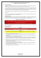
SBS-800 Series Operator & Planned Maintenance Handbook Chapter 3: Overview 3 Overview 3.1 Unit Identification This handbook details SBS-800 SharpEye™ systems comprising of Fibre S-Band and Fibre GaN X-Band transceivers X or S-Band low profile antenna LPA-A37 all variants LPA-A55 all variants LPA-A3 all variants Note: An S-Band LPA is shown for reference; the label is in the same position on X-Band antennas.
SBS-800 Series Operator & Planned Maintenance Handbook Chapter 3: Overview 3.3 Analogue & GaAs SharpEye™ Systems This handbook details SBS-800 SharpEye™ system comprising of S-Band Fibre and X-Band GaN transceivers Earlier SBS-800 systems were fitted with GaAs and analogue SharpEye™ transmission systems which carry different part numbers. These are detailed in previous versions of the SBS-800 handbooks as detailed below.
SBS-800 Series Operator & Planned Maintenance Handbook Chapter 3: Overview Page intentionally blank KH-1601-2 Issue 6 Page 19 of 80
SBS-800 Series Operator & Planned Maintenance Handbook Chapter 3: Overview 3.5 Typical Systems 3.5.
SBS-800 Series Operator & Planned Maintenance Handbook Chapter 3: Overview SBS-800-1 X-Band Doppler SharpEyeTM with 3.7m low profile antenna The SBS-800-1 system comprises of an X Band SharpEyeTM Transceiver/Turning Mechanism incorporating Solid State radar transceiver utilising enhanced Digital Pulse Compression and Pulse Doppler Processing with Kelvin Hughes 3.7m (12ft) Low Profile Antenna (LPA).
SBS-800 Series Operator & Planned Maintenance Handbook Chapter 3: Overview SBS-800-2 X-Band Doppler SharpEyeTM with 5.5m low profile antenna The SBS-800-2 system comprises of an X Band SharpEyeTM Transceiver/Turning Mechanism incorporating Solid State radar transceiver utilising Enhanced Digital Pulse Compression and Pulse Doppler Processing with Kelvin Hughes 5.5m (18ft) Low Profile Antenna (LPA).
SBS-800 Series Operator & Planned Maintenance Handbook Chapter 3: Overview 3.5.
SBS-800 Series Operator & Planned Maintenance Handbook Chapter 3: Overview SBS-800-3 X-Band Doppler & frequency diversity SharpEyeTM with 5.5m low profile antenna The SBS-800-3 system comprises of an X Band SharpEyeTM Transceiver/Turning Mechanism incorporating Solid State radar transceiver utilising Enhanced Digital Pulse Compression, Pulse Doppler Processing and Frequency Diversity with Kelvin Hughes 5.5m (18ft) Low Profile Antenna (LPA).
SBS-800 Series Operator & Planned Maintenance Handbook Chapter 3: Overview 3.5.
SBS-800 Series Operator & Planned Maintenance Handbook Chapter 3: Overview SBS-800-51 S-Band Doppler SharpEyeTM with 3.9m low profile antenna The SBS-800-51 system comprises of an S-Band SharpEyeTM Transceiver/Turning Mechanism enclosure incorporating Solid State radar transceiver utilising Enhanced Digital Pulse Compression and Pulse Doppler Processing with Kelvin Hughes 3.9m (12.8ft) Low Profile Antenna (LPA).
SBS-800 Series Operator & Planned Maintenance Handbook Chapter 4: Switch ON, OFF & Emergency Stop 4 Switch ON, OFF & Emergency Stop 4.1 ANTENNA ROTATION WARNING WARNING ANTENNA ROTATION SAFETY NOTICE When antenna motor power is connected to the system and switched ON, the antenna will rotate immediately regardless of the RUN command status (see conditions below).
SBS-800 Series Operator & Planned Maintenance Handbook Chapter 4: Switch ON, OFF & Emergency Stop 4.2 Switch ON FIRST TIME SWITCH ON Ensure the setting to work of the system has been successfully completed and signed off. POWER Check that all sources of external AC power are available and are switched ON. ANTENNA Ensure the antenna is clear of all obstructions and that it is safe to rotate. TRANSMISSION Ensure it is safe to transmit.
SBS-800 Series Operator & Planned Maintenance Handbook Chapter 4: Switch ON, OFF & Emergency Stop 4.3 Switch OFF SWITCH OFF The following describes how to switch OFF the SBS-800 system for operational purposes. The following does not include the switch OFF/shut down procedures for the track extractor, optional service display or external equipment attached to the system.
SBS-800 Series Operator & Planned Maintenance Handbook Chapter 4: Switch ON, OFF & Emergency Stop 4.4 EMERGENCY ANTENNA STOP In an emergency, antenna rotation and system transmission can be stopped using ANY of the following mechanisms. RDU keyswitch: Place the Antenna Rotation keyswitch on the front of the Radar Distribution Unit into the OFF position. As an additional safety precaution, when in the OFF position the key can be removed.
SBS-800 Series Operator & Planned Maintenance Handbook Chapter 4: Switch ON, OFF & Emergency Stop 4.
SBS-800 Series Operator & Planned Maintenance Handbook Chapter 4: Switch ON, OFF & Emergency Stop Page intentionally blank KH-1601-2 Issue 6 Page 32 of 80
SBS-800 Series Operator & Planned Maintenance Handbook Chapter 5: Anti-Condensation Heater (ACH) 5 Anti-Condensation Heater (ACH) CONNECTION The Anti-Condensation Heater is not connected as standard. The ACH should only be connected where the SBS-800 system is to be switched OFF and left in an un-powered state when high humidity levels are anticipated. Please consult with Kelvin Hughes Ltd for advice on when to connect the anti-condensation heater supply.
SBS-800 Series Operator & Planned Maintenance Handbook Chapter 5: Anti-Condensation Heater (ACH) Page intentionally blank KH-1601-2 Issue 6 Page 34 of 80
SBS-800 Series Operator & Planned Maintenance Handbook Chapter 6: Operation Overview 6 Operation Overview 6.1 Local/Remote Control States Instructions on operating the system in Local and Remote control are detailed in the following sections: Local Control: See Section 7 Remote Control: See Section 8 Service display control: See Section 8.
SBS-800 Series Operator & Planned Maintenance Handbook Chapter 6: Operation Overview 6.2 Switching from Local to Remote Control When Local control is no longer required, the system MUST be switched to Remote. The system can only be changed from Local to Remote control using the switch on the Radar Distribution Unit; it is not possible to remotely change from Local to Remote. Remote Control i.e. command & display or track extractor Local Control i.e.
SBS-800 Series Operator & Planned Maintenance Handbook Chapter 6: Operation Overview 6.4 Transceiver Operational States The following table shows the various operation states of the X or S-Band SharpEye™ transceivers within the gearbox/turning unit: Operation state Description OFF Power is not applied to the transceiver and it is switched OFF. When power is applied to the system, the SharpEye™ initialises and switches to standby or, if any of the self-test checks fail, to fault state.
SBS-800 Series Operator & Planned Maintenance Handbook Chapter 6: Operation Overview 6.5 Performance Monitoring There are no user activated performance monitoring checks in the system. The SharpEye™ transceiver continuously runs background performance checks on forward power, reverse power, receiver sensitivity and temperature. If any of these parameters falls outside predetermined levels a warning message is sent to the Radar Distribution Unit indicating the nature of the fault.
SBS-800 Series Operator & Planned Maintenance Handbook Chapter 7: Local Control 7 Local Control 7.1 Local Control Overview 7.1.
SBS-800 Series Operator & Planned Maintenance Handbook Chapter 7: Local Control 7.1.2 Remote/Local Switch A switch on the front of the Radar Distribution Unit allows the selection of Remote or Local operation. The following explains the basic operation of the system in these two modes. WARNING ANTENNA ROTATION Depending on the position of the safety switches, the antenna will rotate regardless of the position of the Remote/Local or Standby/Run switches.
SBS-800 Series Operator & Planned Maintenance Handbook Chapter 7: Local Control 7.1.3 LCD Panel Operation The LCD display on the front of the RDU is a backlit, two line 16 character display. Push buttons located either side of the display allow the control of the setup menus, local control and status monitoring. The buttons are used in association with the information displayed in the LCD panel, for example in the following picture: - The top right button would select the system status information.
SBS-800 Series Operator & Planned Maintenance Handbook Chapter 7: Local Control 7.1.5 Alarms When the system is in local control Note and an alarm condition exists, the lower right button will flash red and an audible alarm will be generated. VIEW ALARM CONDITION: To view the alarm message/condition, select the status menu and the alarm condition(s) will be displayed in the lower section of the LCD display.
SBS-800 Series Operator & Planned Maintenance Handbook Chapter 7: Local Control 7.2 Menus There are four menus that can be selected from the LCD display; the menus vary depending on system settings. Each menu is detailed in the following sections: Menu availability Menu Local control Control menu Remote Control Status menu Setup menu 7.2.
SBS-800 Series Operator & Planned Maintenance Handbook Chapter 7: Local Control Page intentionally blank KH-1601-2 Issue 6 Page 44 of 80
SBS-800 Series Operator & Planned Maintenance Handbook Chapter 7: Local Control 7.2.
SBS-800 Series Operator & Planned Maintenance Handbook Chapter 7: Local Control 7.2.3 STATUS Menu The STATUS MENU on the Radar Distribution Unit is used by the operator or the system maintainer to view but not configure or adjust the current system settings. The Status menu is available on the RDU in both the REMOTE and LOCAL setting. or When Status is selected from the front panel, the various functions shown below can be selected and viewed as described in section 7.1.5.
SBS-800 Series Operator & Planned Maintenance Handbook Chapter 7: Local Control 7.2.3.2 Radar Control Status Status Menu Status Radar Control Status SharpEye Network NTP Status Comms status MISM status Software Info Exit By scrolling through the radar control status menus, the following system configurations and settings can be viewed but not adjusted. A full description of each function is shown in the Control menu section 7.2.4.
SBS-800 Series Operator & Planned Maintenance Handbook Chapter 7: Local Control 7.2.3.3 SharpEye Status Menu Status Radar Control Status SharpEye Network NTP Status Comms status MISM status Software Info Exit By scrolling through the SharpEye menus, the following system conditions can be viewed but cannot be adjusted.
SBS-800 Series Operator & Planned Maintenance Handbook Chapter 7: Local Control SharpEye (continued) Status 5: Times ON Time Run-time Status 8: Temp FPGA 1 temp FPGA 2 temp Status 11: Skew Mute Secs 7.2.3.4 xxx.
SBS-800 Series Operator & Planned Maintenance Handbook Chapter 7: Local Control 7.2.3.5 NTP Time Status Menu Radar Control Status Status SharpEye Network NTP Status Comms status MISM status Software Info Exit The configuration of the NTP time status can be viewed but not adjusted. Time Stamp ON/OFF Displays the NTP server IP address set during the commissioning of the system Displays the NTP (source) port set during the commissioning of the system Exit the NTP status menu.
SBS-800 Series Operator & Planned Maintenance Handbook Chapter 7: Local Control 7.2.3.7 MISM Status Status Menu Status Radar Control Status SharpEye Network NTP Status Comms status MISM status Software Info Exit By scrolling through the MISM status (Modular Interface System Module) menus, the status of each of the 12 slots on the backplane can be viewed. The results will vary depending on the cards fitted within the RDU.
SBS-800 Series Operator & Planned Maintenance Handbook Chapter 7: Local Control 7.2.3.8 Software Info Status Menu Status Radar Control Status SharpEye Network NTP Status Comms status MISM status Software Info Exit By scrolling through the software info menus, the various software versions for the system can be identified: MISB backplane Software identification number for the backplane (e.g. ZM-2843 V8.
SBS-800 Series Operator & Planned Maintenance Handbook Chapter 7: Local Control 7.2.4 CONTROL Menu When operating in Local mode, the CONTROL MENU on the Radar Distribution Unit is used by the maintainer to adjust the system settings. MENU AVAILABILITY The control menu is only available on the RDU when the Remote/Local switch is set to Local and the service display is off-line, is not connected or is switched OFF. When Remote is selected, the Control menu is not available.
SBS-800 Series Operator & Planned Maintenance Handbook Chapter 7: Local Control 7.2.4.2 TX Power Control Menu Range Mode Tx Power Tx Freq. Mute Rain Sea Int. Rejection Sweep RPM Exit The output power of the SharpEyeTM transceiver can be switched between High (default) and Low. High power: The SharpEyeTM transceiver transmits at full power; this is the recommended default setting.
SBS-800 Series Operator & Planned Maintenance Handbook Chapter 7: Local Control 7.2.4.4 Mute Control Menu Range Mode Tx Power Tx Freq. Mute Rain Int. Sea Rejection Sweep RPM Exit The Mute function allows a 360° transmission inhibit to be Enabled/Disabled. Mute ON: Transmission is muted/stopped i.e. no RF is radiated from the antenna however the antenna continues to rotate. The RED Mute LED on the front of the RDU illuminates. Mute OFF: The system transmits fully for 360°.
SBS-800 Series Operator & Planned Maintenance Handbook Chapter 7: Local Control 7.2.4.6 Int. Rejection Control Menu Range Mode Tx Power Tx Freq. Mute Rain Sea Int. Rejection Sweep RPM Exit THIS MENU IS NOT ENABLED IN SBS-800 SYSTEMS. This menu is not enabled as the system uses Doppler principles automatically. This menu will have no function in this system. 7.2.4.7 Sweep Control Menu Range Mode Tx Power Tx Freq. Mute Rain Sea Int.
SBS-800 Series Operator & Planned Maintenance Handbook Chapter 7: Local Control 7.2.4.8 RPM Control Menu Range Mode Tx Power Tx Freq. Mute Rain Sea Int. Rejection Sweep RPM Exit The RPM function allows the operator to stop rotation (OFF), select Auto or one of three pre-defined antenna rotation speeds. Note 1 Antenna speeds are configured at the factory and are enabled or disabled during setting to work (refer to KH-1601-3 for more information).
SBS-800 Series Operator & Planned Maintenance Handbook Chapter 7: Local Control Page intentionally blank KH-1601-2 Issue 6 Page 58 of 80
SBS-800 Series Operator & Planned Maintenance Handbook Chapter 8: Remote Control 8 Remote Control When the Radar Distribution Unit is set to Remote operation, the external command and display system or track extractor has control of the system. For test purposes, the optional service display can be configured for Remote control and be connected to the track extractor (TE) port to test the serial port functionality.
SBS-800 Series Operator & Planned Maintenance Handbook Chapter 8: Remote Control Page intentionally blank KH-1601-2 Issue 6 Page 60 of 80
SBS-800 Series Operator & Planned Maintenance Handbook Chapter 9: Planned Maintenance 9 Planned Maintenance 9.1 Overview and Safety Notices This section provides information on the planned maintenance for all standard systems within the SBS-800 range. MAINTENANCE RECORD The following pages have been designed to be printed, completed and stored as a maintenance record for standard systems.
SBS-800 Series Operator & Planned Maintenance Handbook Chapter 9: Planned Maintenance 9.
SBS-800 Series Operator & Planned Maintenance Handbook Chapter 9: Planned Maintenance STANDARD ANTENNA SUB-SYSTEM INSPECTION Task Description Pass Fail ☐ ☐ Ensure that all external fastenings are tights, secure and show no signs of severe corrosion or damage. ☐ ☐ Check that waveguide couplings are securely fastened and appear to be waterproof.
SBS-800 Series Operator & Planned Maintenance Handbook Chapter 9: Planned Maintenance TRANSCEIVER/GEARBOX INSPECTION Task General cleaning Description Pass Fail Clean all exterior surfaces with a soft cloth moistened in a mild nonabrasive soap solution. ☐ ☐ Ensure that all securing bolts for the transceiver/gearbox and antenna are secure and show no signs of severe corrosion or damage. Pay particular attention to the four bolts that hold the transceiver gearbox assembly to the deck/mounting plate.
SBS-800 Series Operator & Planned Maintenance Handbook Chapter 9: Planned Maintenance RADAR DISTRIBUTION UNIT (RDU) Task Description Pass Fail External surfaces Clean with a soft, non-abrasive cloth lightly moistened in a mild soap solution. ☐ ☐ Internal surfaces Open the door of the Radar Distribution Unit using a screwdriver. Clean the unit using blower and/or soft brush. ☐ ☐ Ensure that all mounting bolts are secure. ☐ ☐ Ensure all connectors are securely in place.
SBS-800 Series Operator & Planned Maintenance Handbook Chapter 9: Planned Maintenance VF-nC3 Single Phase Inverter (SBS-A229): Checking the fan run-time - On the static inverter control panel, open the small access door, press the MODE button twice and ensure that Fr-F is displayed - Rotate the thumb wheel until FE14 is displayed then press the thumbwheel to access the fan menu. The run-time will be indicated by tx.xx where: T0.01 = 1 hour, t1.00 = 100 hours.
SBS-800 Series Operator & Planned Maintenance Handbook Chapter 9: Planned Maintenance MAN ALOFT SWITCH Task Description Pass Fail Physical inspection Ensure that all fastenings are secure and show no signs of severe corrosion or damage. ☐ ☐ Switch action Ensure the switch operation is smooth and that both the Free and OFF positions can be selected.
SBS-800 Series Operator & Planned Maintenance Handbook Chapter 9: Planned Maintenance SAFETY SWITCH TESTS SYSTEM CONFIGURATION The following tests should be carried out with power restored to the system and the transceiver placed into RUN. WARNING: When carrying out the following test, do not contravene any health and safety precautions regarding working aloft, antenna or electrical safety.
SBS-800 Series Operator & Planned Maintenance Handbook Chapter 9: Planned Maintenance 9.3 10-year Maintenance CHANGING THE STATIC INVERTER IN THE RDU In addition to the annual maintenance requirements indicated earlier in this section, after 10-years of use, the static inverter located within the Radar Distribution Unit must be changed as over time, the electrolytic capacitors within the inverter can dry out.
SBS-800 Series Operator & Planned Maintenance Handbook Chapter 9: Planned Maintenance 9.4 Earth Bonding Maintenance Where an earth/chassis bonding point has been found to be corroded or fails a conductivity test, the bonding joint should be dismantled, cleaned and reassembled as follows: CAUTION ISOLATE THE SYSTEM BEFORE COMMENCING THIS TASK. Under no circumstances should straps or equipment be disconnected from earth/chassis before all power supplies including UPS supplies are isolated at source.
SBS-800 Series Operator & Planned Maintenance Handbook Chapter 10: Contact Details 10 Contact Details Kelvin Hughes Ltd Voltage 6 Mollison Avenue Enfield EN3 7XQ UNITED KINGDOM Phone: +44 (0)1992 805 200 Fax +44 (0) 1992 805 310 Service Technical Advice Spares Internet email surveillance.support@kelvinhughes.co.uk Phone +44 (0)1992 805 200 email Phone surveillance.tech@kelvinhughes.co.uk +44 (0)1992 805 200 email surveillance.support@kelvinhughes.co.uk Phone +44 (0)1992 805 200 Website www.
SBS-800 Series Operator & Planned Maintenance Handbook Chapter 10: Contact Details Page intentionally blank KH-1601-2 Issue 6 Page 72 of 80
SBS-800 Series Operator & Planned Maintenance Handbook Chapter 11: Abbreviations 11 Abbreviations The following abbreviations are used in Kelvin Hughes publications. Some may not appear in this handbook and are shown for reference only.
SBS-800 Series Operator & Planned Maintenance Handbook Chapter 11: Abbreviations NAV Nm NMT NORM N-UP OOW OS PC PCB PI PL PM POS PPI PPR PRF PWM PWR RAD RADAR RACON RAL RCDS R CRS RDU REF REL RF RIP RL RM RM(R) RM(T) RNC RNG ROT RPM RR R SPD RTD Rx SART SAT SBS SC/SC SEL SETD SOG Navigation Nautical Mile Not More Than Normal North-UP Officer On Watch Own Ship Personal Computer Printed Circuit Board Parallel Index Line(s) Pulse Length Performance Monitor Position Planned Position Indicator Pulses Per Revolu
SBS-800 Series Operator & Planned Maintenance Handbook Chapter 12: Index 12 Index French ..............................11 A AC supply isolation............... 31 Adverse weather - Checks after... ............................... 61 Alarms Silence audio.................... 42 View alarm condition ........ 42 Antenna Emergency STOP ............ 30 Isolation .............................. 7 Radiation hazard ................ 6 Rotates at switch on ......... 27 Rotation safety notice .........
SBS-800 Series Operator & Planned Maintenance Handbook Chapter 12: Index Page intentionally blank KH-1601-2 Issue 6 Page 76 of 80
SBS-800 Series Operator & Planned Maintenance Handbook Chapter 12: Index NOTES (Page 1 of 2) KH-1601-2 Issue 6 Page 77 of 80
SBS-800 Series Operator & Planned Maintenance Handbook Chapter 12: Index NOTES (Page 2 of 2) KH-1601-2 Issue 6 Page 78 of 80
SBS-800 Series Operator & Planned Maintenance Handbook Chapter 12: Index Page intentionally blank KH-1601-2 Issue 6 Page 79 of 80
Kelvin Hughes Limited Registered Office: Voltage, 6 Mollison Avenue, Enfield EN3 7XQ, UK. Incorporated in England No.