JS5BD Series 13 SEER User’s Manual / Installation Instructions Split system air conditioner - R-22 IMPORTANT Please read this information thoroughly and become familiar with the capabilities and use of your appliance before attempting to operate or maintain this unit. Keep this literature where you have easy access to it in the future. If a problem occurs, check the instructions and follow recommendations given. If these suggestions don’t eliminate the problem, call your servicing contractor.
USER INFORMATION Important Safety Information.....................................3 Operating Instructions................................................3 Cooling Operation......................................................3 Heating Operation......................................................3 Operating the Air Conditioner for Automatic Cooling and Heating...................................................3 Operating the Indoor Blower Continuously.................3 Turning the Air Conditioner Off....
USER INFORMATION important SAFETY INFORMATION Safety markings are used frequently throughout this manual to designate a degree or level of seriousness and should not be ignored. WARNING indicates a potentially hazardous situation that if not avoided, could result in personal injury or death. CAUTION indicates a potentially hazardous situation that if not avoided, may result in minor or moderate injury or property damage.
INSTALLER INFORMATION important SAFETY INFORMATION INSTALLER: Please read all instructions before servicing this equipment. Pay attention to all safety warnings and any other special notes highlighted in the manual. Safety markings are used frequently throughout this manual to designate a degree or level of seriousness and should not be ignored. WARNING indicates a potentially hazardous situation that if not avoided, could result in personal injury or death.
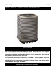
Air conditioner INSTallATION General Information The JS5BD series air conditioner is designed only for outdoor rooftop or ground level installations. This unit has been tested for capacity and efficiency in accordance with A.H.R.I. Standards and will provide many years of safe and dependable comfort, providing it is properly installed and maintained. Abuse, improper use, and/or improper maintenance can shorten the life of the appliance and create unsafe hazards.
Connecting Refrigerant Tubing Between the Indoor & Outdoor Unit CAUTION: This system uses R-22 refrigerant with POE oil. When servicing, cover or seal openings to minimize the exposure of the refrigerant system to air to prevent accumulation of moisture and other contaminants. After outdoor and indoor unit placement has been determined, route refrigerant tubing between the equipment in accordance with sound installation practices.
• • • • • • on the outdoor unit data label. Any other wiring methods must be acceptable to authority having jurisdiction. The outdoor unit requires both power and control circuit electrical connections. Refer to the wiring diagram / schematic for identification and location of outdoor unit field wiring interfaces (Figure 12, page 18). Make all electrical connections in accordance with all applicable codes and ordinances.
3. Set the thermostat fan mode to AUTO and verify the blower stops running. System Cooling 1. Set the thermostat’s system mode to COOL and the fan mode to AUTO. Gradually lower the thermostat temperature setpoint below room temperature and verify the outdoor unit and indoor blower energize. 2. Verify blower wheel is spinning in direction indicated by arrow. Feel the air being circulated by the indoor blower and verify that it is cooler than ambient temperature. Listen for any unusual noises.
Air conditioner MAINTENANCE WARNING: To prevent electrical shock, personal injury, or death, disconnect all electrical power to the unit before performing any maintenance or service. The unit may have more than one electrical supply. Proper maintenance is important to achieve optimum performance from the air conditioner.The ability to properly perform maintenance on this equipment requires certain mechanical skills and tools. If you do not possess these skills, contact your dealer for maintenance.
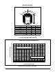
FIGURES & TABLES DO NOT OBSTRUCT TOP OF UNIT Allow adequate clearance for airflow W D H Model Number JS5BD- Height -H- Width -W- Depth -D- 018KA 23" 22 3/4" 22 3/4" 024KB 23" 22 3/4" 22 3/4" 030KB 27" 22 3/4" 22 3/4" 036KB 27" 22 3/4" 22 3/4" 042KA 31" 30 3/4" 30 3/4" 048KA 060KA 31" 43" 30 3/4" 30 3/4" 30 3/4" 30 3/4" Figure 4.
JS5BD-024KB SERIES CHARGING CHART 400 380 Liquid Pressure (psig) 360 Remove refrigerant when above curve 340 320 300 280 260 240 220 Add refrigerant when below curve 200 180 160 140 75 80 85 90 95 100 105 110 115 120 125 130 135 Liquid Temperature (F) Figure 6.
JS5BD-036KB SERIES CHARGING CHART 400 380 Liquid Pressure (psig) 360 Remove refrigerant when above curve 340 320 300 280 260 240 220 Add refrigerant when below curve 200 180 160 140 75 80 85 90 95 100 105 110 115 120 125 130 135 Liquid Temperature (F) Figure 8.
JS5BD-048KA SERIES CHARGING CHART 400 380 Liquid Pressure (psig) 360 Remove refrigerant when above curve 340 320 300 280 260 240 220 Add refrigerant when below curve 200 180 160 140 75 80 85 90 95 100 105 110 115 120 125 130 135 Liquid Temperature (F) Figure 10.
FIGURES & TABLES Refrigerant Charging tables Shaded boxes indicate flooded conditions. Rated design values. The suction pressure will vary from design value if indoor air flow, entering dry bulb, or entering wet bulb temperatures are lower than design. 1. All pressures are listed in psig and all temperatures in ° F 2. Discharge temperatures greater than charted values indicate an undercharged system. OUTDOOR TEMPERATURE (° F) Suct. Press. 70 75 80 85 90 95 100 105 Liq. Dis. Liq. Dis. Liq. Dis. Liq.
Refrigerant Charging tables Shaded boxes indicate flooded conditions. Rated design values. The suction pressure will vary from design value if indoor air flow, entering dry bulb, or entering wet bulb temperatures are lower than design. 1. All pressures are listed in psig and all temperatures in ° F 2. Discharge temperatures greater than charted values indicate an undercharged system. OUTDOOR TEMPERATURE (° F) Suct. Press. 70 75 80 85 90 95 100 105 Liq. Dis. Liq. Dis. Liq. Dis. Liq. Dis. Liq. Dis.
Refrigerant Charging tables Shaded boxes indicate flooded conditions. Rated design values. The suction pressure will vary from design value if indoor air flow, entering dry bulb, or entering wet bulb temperatures are lower than design. 1. All pressures are listed in psig and all temperatures in ° F 2. Discharge temperatures greater than charted values indicate an undercharged system. OUTDOOR TEMPERATURE (° F) Suct. Press. 70 75 80 85 90 95 100 105 Liq. Dis. Liq. Dis. Liq. Dis. Liq. Dis. Liq. Dis.
OUTDOOR TEMPERATURE (° F) Suct. Press. 70 75 80 85 90 95 100 105 Liq. Dis. Liq. Dis. Liq. Dis. Liq. Dis. Liq. Dis. Liq. Dis. Liq. Dis. Liq. Dis. Press. Temp. Press. Temp. Press. Temp. Press. Temp. Press. Temp. Press. Temp. Press. Temp. Press. Temp.
WIRING DIAGRAM Split System Air Conditioner (Outdoor Section) Single Phase NOTES: Optional Hard Start Kit 1. Couper le courant avant de faire letretien. 1. Disconnect all power before servicing. 2. Employez uniquement des conducteurs 2. For supply connections use copper conductors only. to “H” on capacitor en cuivre. 3. Not suitable on systems that exceed 150 volts to ground. RED 3. Ne convient pas aux installations 4. For replacement wires use conductors suitable for 105 deg C.
Specifications & illustrations subject to change without notice or incurring obligations. O’ Fallon, MO | Printed in U.S.A.