B6BM, B6EM, & B6VM SERIES INSTALLATION INSTRUCTIONS AIR HANDLER IMPORTANT ATTENTION INSTALLERS: It is your responsibility to know this product better than your customer. This includes being able to install the product according to strict safety guidelines and instructing the customer on how to operate and maintain the equipment for the life of the product. Safety should always be the deciding factor when installing this product and using common sense plays an important role as well.
TABLE OF CONTENTS IMPORTANT SAFETY INFORMATION......................3 REQUIREMENTS & CODES......................................3 GENERAL INFORMATION.........................................4 Before You Install this Unit........................................4 Locating the Air Handler...........................................4 Minimum Clearances................................................4 Operation of Air Handler During Construction..........4 Installation in a Garage.................................
IMPORTANT SAFETY INFORMATION Please read all instructions before servicing this equipment. Pay attention to all safety warnings and any other special notes highlighted in the manual. Safety markings are used frequently throughout this manual to designate a degree or level of seriousness and should not be ignored. WARNING indicates a potentially hazardous situation that if not avoided, could result in personal injury or death.
GENERAL INFORMATION This appliance has been tested for capacity and efficiency in accordance with AHRI Standards and will provide many years of safe and dependable comfort, providing it is properly installed and maintained. Abuse, improper use, and/or improper maintenance can shorten the life of the appliance and create unsafe hazards. Please read all instructions before installing the unit.
• Before occupying the structure: The filter must be replaced or cleaned, the duct work must be inspected and cleaned of any construction debris, and the air handler must be cleaned and/or repaired if found to be dirty, damaged, or malfunctioning in any way by a qualified HVAC technician. The air handler shall be inspected and approved by applicable local authority even if this requires redundant inspections.
pressure drop in the duct system. Care must be taken to maintain the proper maximum pressure rise across the air handler, temperature rise and flow rate. This may mean increasing the duct size and/or reducing the blower speed. These treatments must be constructed and installed in accordance with NFPA and SMACNA construction standards. Consult with local codes for special requirements.
Horizontal Installations The B6 Series air handler can be installed horizontally in an attic, basement, crawl space or alcove. It can also be suspended from a ceiling in a basement or utility room in either a right to left airflow or left to right airflow as shown in Figure 3. Air handlers may or may not be shipped from the factory with all the parts required for horizontal left applications and horizontal right applications.
7. Insert the plug (from horizontal drain pan) into the open and unused drain hole in the drain pan at the bottom of the unit to block bypass air. 8. Remove the corresponding drain line knockout from the coil access door to allow access to the horizontal drain. 9. Replace the door and attach the drain line WARNING: NITROGEN HEALTH 1 FLAMMABILITY 0 REACTIVITY 0 0 Minimal Hazard 1 Slight Hazard The coil in the air handler is factory shipped with a nitrogen charge.
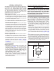
Connecting the Linesets Figure 6. Restrictor Insertion into Distributor Body IMPORTANT NOTES FOR HORIZONTAL OR DOWNFLOW INSTALLATIONS WITH TXV VALVE: • The sensing bulb must be located flush against the suction line for optimum heat transfer. • Avoid attaching the sensing bulb to the lowest part of the suction line where condensate may accumulate. • Do not locate the sensing bulb on vertical sections of the lineset.
8. Evacuate the system of moisture and non-condensables to prevent low efficiency operation or damage to the unit. The suggested range of evacuation is 350 - 500 microns. 9. Charge the system with refrigerant. Refer to the outdoor unit installation manual for additional charging instructions. 10. Check the system for leaks, including the lineset and the brazed joints. 11. Replace all grommets and properly dispose of all removed parts.
ELECTRICAL CONNECTIONS WARNING: ELECTRICAL SHOCK, FIRE OR EXPLOSION HAZARD Failure to follow safety warnings exactly could result in serious injury or property damage. Improper servicing could result in dangerous operation, serious injury, death or property damage. • Before servicing, disconnect all electrical power to the indoor blower. • When servicing controls, label all wires prior to disconnecting. Reconnect wires correctly. • Verify proper operation after servicing.
Refer to the thermostat manufacturer’s instruction sheet for detailed mounting and installation information. • Install the grommet, which is packed with the unit, in the hole for low-voltage wires. Properly connect the low-voltage wiring between the thermostat, outdoor unit, and control board. NOTE: When the low voltage wires are positioned in this grommet, the grommet will prevent chafing and/or shorting of the low voltage leads.
When electric heat packages with circuit breakers are field-installed, the circuit breaker may be used as a disconnecting means in most applications. Reference the NEC and local codes for disconnect requirements. If a heater kit is installed: The B6BM air handler is shipped from the factory without an electric heater kit installed. If Electric heat is desired, the H6HK heater kit may be purchased separately and field installed.
5. Weigh in the proper amount of new (or reclaimed) refrigerant. Refer to the air conditioner or heat pump installation manual for the proper type and quantity of refrigerant. Refrigerant Charging The system refrigerant charge can be checked and adjusted through the service ports provided at the front panel of the outdoor unit. Use only gauge lines which have a Schrader depression device present to actuate the valve.
• • • Terminal 4 = Hi speed Terminal 5 = Med speed Terminal 6 = Low speed 4. Replace the upper door and secure it to the unit. 5. Restore power to the unit. High Efficiency Units (Variable & Fixed Speed) IMPORTANT! This air handler has been designed to give the installer maximum flexibility to optimize system performance, efficiency, and comfort. Because there are so many different ways to set up the air handler it is important to read and follow these directions carefully.
UNIT MAINTENANCE Proper maintenance is most important to achieve the best performance from a air handler. Some of the components and their locations are shown in Figure 12 (page 18). If any component of the air handler must be replaced, use only factory authorized replacement parts specified in the Replacement Parts List provided online. WARNING: ELECTRICAL SHOCK, FIRE OR EXPLOSION HAZARD Failure to follow safety warnings exactly could result in serious injury or property damage.
FIGURES & TABLES 3/4” 3/4” 3/4” 13” 11/8” K.O. (typ.) “A” 1 7/8" K.O. 11/4” 15/8” 17/8” 2 5/8” 1 7/8” 5 5/8” 3 5/8” 11/4” 3 1/4” 1 1/8” 7/8" K.O. 11/8” K.O. (typ.) 1 7/8” 13/4” K.O. (typ.) DETAIL “D” “H” 3 1/4” 2 1/4” SUCTION LIQUID 15 1/4” 13” “W” 22" CABINET SIZE H W A DETAIL D A B 43-5/16 14-3/16 12-3/4 No 43-5/16 19-11/16 18-1/4 No Tall B 49-5/16 19-11/16 18-1/4 No C 55-15/16 22-7/16 21 Yes Figure 11.
Circuit Breaker (60A) Heating Element Assembly Transformer Motor Control Board Upper Door Assembly Blower Wheel Control Board Capacitor Motor Mount Kit Blower Housing Coil Assembly Horizontal Drain Pan Vertical Drain Pan Filter Tracks Lower Door Assembly Figure 12.
Airflow Data DRY COIL ESP *24K A-CABINET *30K A-CABINET *24K B-CABINET *30/*36K B-CABINET *42/48K B-CABINET *48K C-CABINET *60K C-CABINET 0.10 0.20 0.30 0.40 0.50 0.60 0.70 0.80 Low Corrected ESP1 Medium Corrected ESP1 High Corrected ESP1 Low Corrected ESP1 Medium Corrected ESP1 High Corrected ESP1 683 0.00 861 0.00 1072 0.00 849 0.00 1118 0.00 1277 0.00 647 0.07 823 0.00 1026 0.00 825 0.04 1087 0.00 1233 0.00 607 0.19 781 0.11 975 0.00 793 0.15 1046 0.04 1184 0.00 563 0.30 734 0.
COOLING OR HEATING AIRFLOW (CFM) SWITCH SETTINGS 0 = OFF, 1 = ON B6EM A-CABINET DRY COIL ESP 1/5 2/6 3/7 4/8 0.1 0.2 0.3 0.4 0.5 0.6 0.
CABINET NOMINAL ELECTIC HEAT KW 5 8 10 15 20 25 30 A 800 900 1000 1300 N/A N/A N/A B C 900 1000 1000 1100 1100 1200 1300 1400 1500 1600 N/A 1800 N/A 2000 NOTE: See Table 6 for appropriate switch settings for these airflows. Table 7.
COOLING AIRFLOW A/B SWITCH SETTING 0 = OFF, 1 = ON B6VM A-CABINET 0 0 0 0 0 0 0 0 0 0 0 0 0 0 0 0 HEATING AIRFLOW COOL SWITCH SETTING 0 = OFF, 1 = ON 5 6 7 8 0 0 0 0 0 0 0 0 1 1 1 1 1 1 1 1 0 0 0 0 1 1 1 1 0 0 0 0 1 1 1 1 0 0 1 1 0 0 1 1 0 0 1 1 0 0 1 1 0 1 0 1 0 1 0 1 0 1 0 1 0 1 0 1 AIRFLOW (CFM) A/B SWITCH SETTING HEATER KIT 0 = OFF, 1 = ON INSTALLED (KW) 0 0 0 0 0 0 0 0 525 560 600 625 700 750 800 850 875 890 930 950 1000 1050 1125 1200 COOLING AIRFLOW A/B SWITCH SETTING 0 = OFF, 1 = ON
Electrical Diagrams & Data P2 R C G W 3A Fuse Y BLWDTC BLWDTC_R L2 L1 EAC COOL HEAT LED 1 HEATER P1 Figure 13. Single Stage Control Board R G Y/2Y O W1 W2 Y1 L 3A Fuse C P3 EAC HUM L2 P2 LED 1 HEATER P1 Figure 14.
TEST PORT R W1 NOT USED FAN SPEED GREEN RED OFF ON TWIN DEHUM Y1 C EXPANSION PORT 1 2 3 4 5 6 78 HEAT COOL STATUS BLOWER MOTOR Figure 15. Fixed Speed Motor Control Board STATUS LIGHTS L2-OUT L2-IN GREEN RED Y/Y2 RED OUTPUTS W L1-IN Y1 L1-OUT H 2 3 4 5 6 78 HEAT Y1 COOL SENSOR C GND EXPANSION PORT BLOWER MOTOR Figure 16.
Field Wiring Factory Wiring: Low Voltage High Voltage Legend IF BOARD EQUIPPED WITH BLWDTC TERMINAL BLACK Air Handler R BLW DTC YELLOW W G C HEATER PLUG 7654321 Y R WHITE GREEN GRAY RED WIRING DIAGRAM RELAY 4-PIN PLUG (18) RELAY Figure 17. B6BM Wiring Diagram 25 L1 L2 R C L2 L1 HEAT COOL EAC 2 1 RED BLACK CAP. BROWN BROWN RED 3-SPEED MOTOR 1=COM 2=CAP. 3=CAP.
240 24 V C GRAY RED Figure 18. B6EM Wiring Diagram TWIN R C Y DEHUM L1 Field Wiring Factory Wiring: Low Voltage High Voltage R L1 L2 C R BLACK MOTOR EXPANSION TEST WHITE HARNESS 1 2 3 4 5 6 HARNESS 6-PIN PLUG 1 2 3 4 5 6 WHITE BLACK MOTOR GREEN 9-PIN HOUSING 9-PIN PLUG 6-PIN PLUG 7110760 0510 NOTES: 1. The blower motor speed tap connection may not be as shown. See the Installation Instructions. 2. Disconnect all power before servicing. 3.
L2 HUM EAL HARNESS BLACK RED Legend Field Wiring Factory Wiring: Low Voltage High Voltage R 24 V WHITE BLACK COM RED C TRANSFORMER 240 208 L1 L2 C R EXPANSION NOTES: 1. The blower motor speed tap connection may not be as shown. See the Installation Instructions. 2. Disconnect all power before servicing. 3. Transformer may havea dual voltage primary tap. Match the tap position with the supply voltage used. 4. If the internal wiring is replaced, use only 105°C copper wire of the same gauge.
B6BM MINIMUM CIRCUIT AMPACITY & MAXIMUM OVERCURRENT PROTECTION 240 VAC, 50 & 60 HZ, SINGLE PHASE CIRCUIT C SINGLE CIRCUIT 60 CIRCUIT B C CIRCUIT A 48 SINGLE CIRCUIT C CIRCUIT C 42/48 CIRCUIT B B CIRCUIT A 30/36 SINGLE CIRCUIT B CIRCUIT C 30 CIRCUIT B A CIRCUIT A 24 SINGLE CIRCUIT B 1.6 26.6 41.2 51.6 1.6 26.6 41.2 51.6 3.1 28.1 42.7 53.1 53.1 2.6 27.6 42.2 52.6 52.6 52.6 3.1 28.1 42.7 53.1 53.1 53.1 5.4 30.4 45.0 55.4 55.4 55.4 55.4 55.4 6.3 31.3 45.8 56.3 56.3 56.3 56.3 56.
B6(E,V)M MINIMUM CIRCUIT AMPACITY & MAXIMUM OVERCURRENT PROTECTION 240 VAC, 50 & 60 HZ, SINGLE PHASE 15 30 45 60 80 35 50 15 30 45 60 80 110 35 50 15 35 50 60 90 110 150 175 35 50 4.8 26.4 39.1 48.1 48.1 4.8 26.4 39.1 48.1 48.1 48.1 6.8 28.4 41.1 50.1 50.1 50.1 50.1 50.1 - 4.8 26.4 39.1 48.1 21.7 69.8 28.2 42.3 4.8 26.4 39.1 48.1 21.7 69.8 43.3 91.4 28.2 42.3 6.8 28.4 41.1 50.1 21.7 71.8 43.3 93.4 43.3 21.7 115.1 43.3 43.3 136.8 30.2 44.
CONTROL SIGNAL & MODE OPERATION TOTAL KW 5 KW 10 KW 15 KW 20 KW W1 & W2 EHEAT ON 25 KW 30 KW OFF — 5 KW 10 KW 15 KW 20 KW W1 & Y/Y2 AUX HEAT ON 25 KW 30 KW OFF — BOARD ACTION Stage 1 Heat on instantly Heat blower on after 3 second delay Stage 1 Heat on instantly Heat blower on after 3 second delay Stage 2 Heat on after 5 seconds delay Stage 1 Heat on instantly Heat blower on after 3 second delay Stage 2 Heat on after 5 seconds delay Stage 3 Heat on after 10 seconds delay Stage 1 Heat on inst
CONTROL SIGNAL & MODE OPERATION TOTAL KW 5 KW 10 KW 15 KW 20 KW W1, W2 & Y/Y2 AUX HEAT ON 25 KW 30 KW G FAN Y/Y2 HEAT PUMP & COOL Y1 HEAT PUMP & COOL Y1 & Y/Y2 HEAT PUMP & COOL OFF — ON OFF ON OFF ON OFF ON OFF — — — — — — — — BOARD ACTION Stage 1 Heat on instantly Cool blower on after 3 second delay Stage 1 Heat on instantly Cool blower on after 3 second delay Stage 2 Heat on after 5 seconds delay Stage 1 Heat on instantly Cool blower on after 3 second delay Stage 2 Heat on after 5 seconds del
INSTALLATION / PERFORMANCE CHECK LIST INSTALLER NAME: ATTENTION INSTALLERS: It is your responsibility to know this product better than your customer. This includes being able to install the product according to strict safety guidelines and instructing the customer on how to operate and maintain the equipment for the life of the product. Safety should always be the deciding factor when installing this product and using common sense plays an important role as well.