
Instructions / Assembly


6
AIR HANDLER INSTALLATION
The B6 Series Air Handler is shipped ready for vertical
upflow installation and is approved for attic, basement,
alcove/closet or crawlspace installation with zero clearance
to combustibles. See Table 1, (page 4) for required
installation clearances. This appliance is approved only
for indoor use.
• Theunitmustbeleveledatinstallationandattachedto
a properly installed duct system.
• Thesurfacethattheairhandlerismountedonmust
provide sound physical support of the unit.
• Theairhandlermustbeinstalledsothatallelectrical
components are protected from water.
• Ifalouvereddoorisinstalledacrossthefrontofthis
unit, the appliance must be mounted flush or behind
front edge of finished wall.
• Always reinstall the doors on the air handler after
servicing or cleaning/changing the filters. Do not operate
the air handler without all doors and covers in place.
Packaging Removal
Remove the shipping crate and User’s Manual from the
equipment. When removing the crate, use extra care so
tubing connections are not damaged. Do not pull on the
coils upper tubes.
Mounting Applications
Vertical only air handlers are factory ready for upflow
applications. These units may be applied in downflow
applications when applied with the appropriate field kit.
Factory ready horizontal air handlers may be applied in
upflow or horizontal-left and -right discharge applications.
These units may also be applied in downflow discharge
when applied with the appropriate field kit as specified in
the units Technical Specifications.
Through-the-floor installations require a 1/4” thick
noncombustible resilient gasket to be used whenever the
supply or return air ducts pass through the floor. The gasket
should be positioned between the duct, unit, and floor.
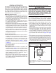
Upflow Installations
All air handlers are factory shipped, ready for upflow
installation. The horizontal drain pan may be removed
from the air handler when installing the unit in an upflow
configuration. All return air must enter from the bottom of
the unit. A typical upflow unit is shown in Figure 1.
Downflow Installations
The downflow accessory kit (See Technical Specifications)
is required for downflow applications. Instructions for
installing the downflow accessory kit are included with the
kit. It is recommended that the accessory be installed prior
to installing the unit. All return air in downflow applications
must enter through the top of the unit. A typical installation
of the unit in a downflow application is shown in Figure 2.
Horizontal
Drain Pan
Return
Air
Figure 1. Upflow Installation
Figure 2. Downflow Installation
Tube
Close-off
Plate
Coil
Cabinet
Adaptor Kit
pressure drop in the duct system. Care must be taken
to maintain the proper maximum pressure rise across
the air handler, temperature rise and flow rate. This
may mean increasing the duct size and/or reducing the
blower speed. These treatments must be constructed
and installed in accordance with NFPA and SMACNA
construction standards. Consult with local codes for
special requirements. For best sound performance, be
sure to install all the needed gaskets and grommets
around penetrations into the air handler, such as for
electrical wiring.