
Instructions / Assembly


10
• Iftheairhandlerislocatedinorabovealivingspace
where damage may result from condensate overflow,
an auxiliary drain pan shall be installed under the unit.
A separate drain line should extend from the pan to a
conspicuous point and serve as an alarm indicating
that the primary drain is restricted. As an alternative to
a separate drain line, an approved water level indicator
or float switch device may be used to shut down the
unit in the event water is detected in the auxiliary pan.
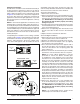
• Installasingle5inchtrapinthecondensatedrainline
as close to the coil as possible. Make sure that the
top of the trap is below the bottom of the drain pan to
prevent the condensate from overflowing the drain pan.
NOTE: There must be only one trap in the drain line.
Using more than one trap may prevent drainage.
• Primethetrapwithwater.Insulatethedrainifitislocated
in an unconditioned space, and test the condensate line
for leaks. Consult local codes for additional restrictions
or precautions.
• During system checkout, inspect the drain line and
connections to verify proper condensate drainage.
8. Evacuate the system of moisture and non-condensables
to prevent low efficiency operation or damage to the
unit. The suggested range of evacuation is 350 - 500
microns.
9. Charge the system with refrigerant. Refer to the
outdoor unit installation manual for additional charging
instructions.
10. Check the system for leaks, including the lineset and
the brazed joints.
11. Replace all grommets and properly dispose of all
removed parts.
Condensate Drainage
CAUTION:
The air handler must be level to ensure proper
condensate drainage. An unlevel installation may
result in structural damage, premature equipment
failure, or possible personal injury.
• Methodsfordisposingofcondensatevaryaccording
to local codes. Refer to local codes or authority having
jurisidiction for restrictions and proper condensate
disposal requirements.
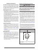
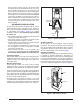
• The drain pan that is supplied with this air handler
contains a primary and secondary drain fitting. The
condensate is drained from the unit through two 3/4”
female pipe fittings located on the front side of the unit
as shown in Figure 8.
• Thedrainpanmustbedrainedwitheldsuppliedtubing
or pvc pipe and adequately trapped. Both drain tubes
must have a minimum diameter of 3/4” and be trapped
separately.
IMPORTANT: Failure to install a trap may result in
condensation overflowing the drain pan, resulting in
substantial water damage to surrounding area.
• Routebothlinestoasuitabledrain,avoidingsharpbends
and pinching of the lines. The drain should maintain a
minimum horizontal slope in the direction of discharge
of not less than 1” vertical for every 10 ft of horizontal
run.
3/4” Adapter w/
3/4” dia. hose barb
3/4” minimum dia.
PVC or flexible tubing
HORIZONTAL
UPFLOW
DOWNFLOW
NOTES:
1. The drain lines must maintain a downward slope to ensure proper
condensate drainage.
2. Each condensate drain must be trapped separately using a J-Trap or
field supplied loop.
Figure 8. Condensate Drainage Example