Single Stage High Efficiency Gas Furnaces 80+ AFUE INSTALLATION INSTRUCTIONS *SA Upflow / Horizontal Furnace WARNING FIRE OR EXPLOSION HAZARD • Failure to follow safety warnings exactly could result in serious injury or property damage. • Installation and service must be performed by a qualified installer, service agency or the gas supplier. • Do not store or use gasoline or other flammable vapors and liquids in the vicinity of this or any other appliance.
TABLE OF CONTENTS IMPORTANT SAFETY INFORMATION....................... 3 REQUIREMENTS & CODES....................................... 3 Combustion Air Quality............................................ 4 Clearances to Combustible Materials...................... 4 Heating Load........................................................... 4 Installation in a Garage............................................ 5 Operation of Furnace During Construction.............. 5 COMBUSTION AIR & VENTING REQUIREMENTS....
IMPORTANT SAFETY INFORMATION INSTALLER: Please read all instructions before servicing this equipment. Pay attention to all safety warnings and any other special notes highlighted in the manual. Safety markings are used frequently throughout this manual to designate a degree or level of seriousness and should not be ignored. WARNING - indicates a potentially hazardous situation that if not avoided, could result in personal injury or death.
• A gas-fired furnace for installation in a residential garage must be installed as specified on page 5. • This furnace is not approved for installation in mobile homes. Installing this furnace in a mobile home could cause fire, property damage, and/or personal injury. • If the furnace is installed in a confined space, it is required that the necessary combustion air come from the outdoors by way of attic, crawl space, air duct, or direct opening.
CLEARANCES TO COMBUSTIBLE MATERIALS UPFLOW & DOWNFLOW APPLICATIONS CAUTION: FRONT FRONT BOTTOM SIDE TOP RIGHT SIDE HORIZONTAL APPLICATIONS VENT VENT LEFT SIDE BACK TOP Operation of Furnace During Construction SIDE Left Side.................. 0 Inches Top............................0 Inches Right Side................ 0 Inches Front......................... †4 Inches Vent......................... 0 Inches Back......................... 0 Inches Allow 24 in. minimum clearance for servicing.
COMBUSTION AIR & venting REQUIREMENTS WARNING: Carbon monoxide poisoning hazard Failure to follow the steps outlined below for each appliance connected to the venting system being placed into operation could result in carbon monoxide poisoning or death. The following steps shall be followed with each individual appliance connected to the venting system being placed in operation, while all other appliances connected to the venting system are not in operation: 1.
Important Information • Provisions must be made during the installation of this furnace that provide an adequate supply of air for combustion. Furnace installation using methods other than those described in the following sections must comply with the National Fuel Gas Code (NFGC) and all applicable local codes. • Instructions for determining the adequacy of combustion air for an installation can be found in the current revision of the NFGC (ANSI Z223.1 / NFPA54).
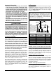
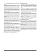
Ventilation louvers at each end of attic Outlet air duct must be at least 1 sq. in. per 4,000 Btuh of total input rating. Must extend above attic insulation Furnace Inlet air duct must be at least 1 sq. in. per 4,000 Btuh of total input rating. Crawl Space 12" Max --- Figure 3. Combustion Air Drawn from a Crawl Space or Vented Attic --- Water Heater Furnace Inlet and Outlet Ducts must extend above attic insulation. Inlet Air Duct must be at least 1 sq. in. per 4,000 Btuh of total input rating.
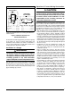
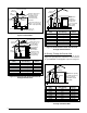
Alternate Method of Providing Air from Outside: Category I Venting If acceptable under local Codes, it is permitted to provide outside air using one opening (See NFGC). Generally, confined spaces must have 2 openings in the space for combustion air. One opening must be within 12 inches of the ceiling, and the other must be within 12 inches of the floor. However, an alternative method recently adopted by the NFGC uses one opening within 12 inches of the top of the space.
• • • • • 10 codes. The minimum diameter of any vent pipe is 4 inches. The venting system should be designed to have the minimum number of elbows or turns. All horizontal runs shall slope upwards from the furnace at ¼ inch per running foot of vent. Supports for the vent pipe must be installed a minimum of every five feet along the vent run to ensure no displacement after installation.
CIRCULATING AIR REQUIREMENTS WARNING: Do not allow combustion products to enter the circulating air supply. Failure to prevent the circulation of combustion products into the living space can create potentially hazardous conditions including carbon monoxide poisoning that could result in personal injury or death. All return ductwork must be secured to the furnace with sheet metal screws. For installations in confined spaces, all return ductwork must be adequately sealed.
Using sharp metal cutters, cut an opening between all 4 knockouts to expose the blower assembly. Position the return air duct over the opening and secure to the side with sheet metal screws. • Bottom Return Installations: If using the bottom of the furnace for return air, the bottom panel (Figure 18) must be removed from the bottom of the furnace. See page 15 for removal instructions. Position the furnace over the return air duct and secure together with sheet metal screws.
Locating the Furnace • The dimensions of the room or alcove must be able to accommodate the overall size of the furnace and required clearances to combustible materials listed in Figure 1 (page 5). Access for positioning and servicing must also be considered when locating the unit. To determine the required clearances needed for installation, refer to Figure 18 (page 26) for overall dimensions.
Downflow Installation The furnace must not be installed directly on carpeting, tile, or any combustible material other than wood flooring. To install the furnace on combustible flooring, a special sub-base is required. WARNING: Nuts (x2) Failure to install the downflow sub-base kit may result in fire, property damage or personal injury. Threaded Rod WARNING: The downflow sub-base kit must not be installed directly on carpeting, tile, or any combustible material other than wood flooring.
Pressure Switch Tubing Figure 10 displays the proper routing of pressure switch tubing for *SA & *SK furnaces. On both furnaces, the tubing connects at one end of the pressure switch and is routed directly onto the static tap of the inducer assembly. Figure 10. Pressure Switch Tubing for *SA & *SK Furnaces Bottom Panel Removal Alternate Bottom Panel Removal The steps listed below explain the proper method for removing the bottom panel from the furnace. See Figure 11. 1.
GAS SUPPLY & PIPING WARNING: FIRE OR EXPLOSION HAZARD • Failure to follow safety warnings exactly could result in serious injury or property damage. • Installation and service must be performed by a qualified installer, service agency or the gas supplier. • Do not store or use gasoline or other flammable vapors and liquids in the vicinity of this or any other appliance. WHAT TO DO IF YOU SMELL GAS • Do not try to light any appliance.
AVERTISSEMENT: RISQUE D’INDENDIE OU D’EXPLOSION Le non-respect des avertissements de sécurité pourrait d’entraîner des blessures graves, la mort ou des dommages matériels. Ne jamais utiliser une flamme nue por vérifier la présence des fuites de gaz. Pour la vérification de tous les joints, utiliser plutôt une solution savonneuse commerciale fabriquée spécifiquement pur la détection des fuites de gaz. Un incendie ou une explosion peut entraîner des dommages matériels, des blessures ou la mort.
UPFLOW MODELS 1 1 180 120 90 60 FLAME BLOWER OFF DELAY 180 120 90 60 8 LOW ML MH HIGH EAC L1 XFMR HUM LOW ML MH HIGH EAC L1 XFMR HUM NEUTRALS L1A 6 3 5 2 4 1 NEUTRALS HEAT COOL FAN BLOWER OFF DELAY See Note STATUS 9 6 3 8 5 2 7 4 1 L1A 8 FLAME 24V 9 6 3 8 5 2 7 4 1 6 3 5 2 4 1 R C Y G W STATUS HEAT COOL FAN 24V R C Y G W See Note 3 3 7 5 5 6 2 2 Left Side Entry 6 Right Side Entry DOWNFLOW MODELS 9 6 3 8 5 2 7 4 1 180 120 90 60 180 120 90 60 LOW ML MH HIGH EAC L1 XFMR H
Conversion to LP / Propane WARNING: The furnace was shipped from the factory equipped to operate on natural gas. Conversion to LP / Propane gas must be performed by qualified service personnel using a factory supplied conversion kit. Failure to use the proper conversion kit can cause fire, explosion, property damage, carbon monoxide poisoning, personal injury, or death. Conversion to LP / Propane is detailed in the installation instructions provided with the conversion kit.
F (40° C). For electrical specifications, refer to the furnace nameplate or Table 2. IMPORTANT NOTES: • An electrical disconnect must be installed readily accessible from and located within sight of the furnace. See Figure 14 or the wiring diagram label inside of the control door. Any other wiring methods must be acceptable to authority having jurisdiction. • Proper line voltage polarity must be maintained in order for the control system to operate correctly.
Thermostat / Low Voltage Connections • The furnace is designed to be controlled by a 24 VAC thermostat. The thermostat’s wiring must comply with the current provisions of the NEC (ANSI/NFPA 70) and with applicable local codes having jurisdiction. • The thermostat must be installed according to the instructions supplied by the thermostat manufacturer. Low voltage connections (24 VAC) from the thermostat are wired to the terminal strip on the integrated control in the furnace.
NOTE: One furnace can be used for one stage of heating and the other furnace can be used for the second stage of heating. The installer also has the choice of running one furnace only or both furnaces. In both cases the blowers will run at the same time and at the same speeds: • Single stage heating: The W connection on each furnace must be connected together and then connected to the W connection of the thermostat. This will allow both furnaces to ignite at the same time for one stage heating.
Capscrew Figure 17. Regulator Capscrew 1. Place thermometers in the return and supply air stream as close to the furnace as possible. The thermometer on the supply air side must be shielded from direct radiation from the heat exchanger to avoid false readings. 2. Adjust all registers and duct dampers to the desired position and run the furnace for 10 to 15 minutes before taking any temperature readings. The temperature rise is the difference between the supply and return air temperatures.
Fan Mode • When the thermostat energizes the G terminal for continuous fan (without calling for heat or cooling), the indoor fan is energized on the selected FAN speed. • If a call for cooling occurs during continuous fan, the blower will switch over to the selected COOL speed. • If the W terminal receives a call for heat during continuous fan, the blower will de energize. • A call for fan is ignored while in lockout.
CAUTION: To prevent damage to the unit or internal components, it is recommended that two wrenches be used when loosening or tightening nuts. Do not over tighten! 6. Using two wrenches, separate the ground-joint union in the gas supply piping at the furnace. 7. Remove the piping between the gas valve and the ground-joint union. (If applicable). 8. Remove all screws securing the burner assembly to the furnace. 9. Carefully remove the burner assembly from the furnace.
FIGURES & TABLES *SA 80+ Upflow Furnace 045C-23A 054C-23A 072C-24B 090C-24B Dim. -A- Dim. -B- Dim. -C- Dim. -D- 14 1/4 10 3/4 12 5/8 12 7/8 TOP VIEW C Front Brace FL 23 17 1/2 11 3/4 15 7/8 16 1/8 21 14 19 3/8 19 7/8 24 1/2 15 1/4 22 7/8 23 1/8 BOTTOM VIEW D AN 19 GE S Bottom Panel 23 1/2 Model #’s 072C-35C 090C-35C B 108C-35C Accepts 4” Type B Vent Pipe T-stat (Ø 7/8) NOTE: Dimensions shown in Inches.
AIRFLOW DATA *SA - UPFLOW / HORIZONTAL FURNACES - 80+ AFUE Model Number & Heating Input (Btuh) SA045C-23A Bottom Return (45,000) SA045C-23A Side Return (45,000) SA054C-23A Bottom Return (54,000) SA054C-23A Side Return (54,000) SA072C)-24B Bottom Return (72,000) SA072C-24B Side Return (72,000) SA090C-24B Bottom Return (90,000) SA090C-24B Side Return (90,000) SA072C-35C Bottom Return (72,000) SA072C-35C Side Return (72,000) SA072C-35C Side + Bottom or 2 Sides (72,000) External Static Pressure (Inc
*SA - UPFLOW / HORIZONTAL FURNACES - 80+ AFUE Model Number Heating Input (Btuh) SA090C-35C Bottom Return (90,000) SA090C-35C Side Return (90,000) SA090C-35C Side + Bottom or 2 Sides (90,000) SA108C-35C Bottom Return (108,000) SA108C-35C Side Return (108,000) SA108C-35C Side + Bottom or 2 Sides (108,000) SA126C-45D Bottom only or 2 openings (126,000) SA126C-45D Side Return (126,000) External Static Pressure (Inches Water Column) Motor Speed 0.1 CFM 0.2 Rise CFM 0.3 Rise CFM 0.5 0.
*SK - DOWNFLOW FURNACES - 80+ AFUE Model Number & Heating Input (Btuh) SK054C-23A (54,000) SK072C-24B (72,000) SK090C-24B (90,000) SK108C-35C (108,000) SK126C-45D (126,000) External Static Pressure (Inches Water Column) Motor Speed 0.1 0.2 0.3 0.5 0.4 0.6 0.7 0.
Yellow LED Continuous Flash On Figure 19.
GAS INFORMATION GAS FLOW RATES GAS FLOW RATES CUBIC FEET PER REVOLUTION OF GAS METER TIME FOR ONE REVOLUTION (SECONDS) 10 12 1 5 10 TIME FOR ONE REVOLUTION (SECONDS) 360 300 1,800 1,500 3,600 3,000 66 68 CUBIC FEET PER REVOLUTION OF GAS METER 1 5 10 55 53 273 265 545 529 14 257 1,286 2,571 70 51 257 514 16 225 1,125 2,250 72 50 250 500 18 200 1,000 2,000 74 49 243 486 20 180 900 1,800 76 47 237 474 22 164 818 1,636 78 46 231 462 24 150 750 1,500
PROPANE DERATION CHART ALTITUDE ABOVE SEA LEVEL 0 to 1,999 FT 2,000 to 2,999 FT 3,000 to 4,999 FT 5,000 to 5,999 FT 6,000 to 7,999 FT 8,000 to 10,000 FT INPUT (BTU) 45,000 54,000 72,000 90,000 108,000 126,000 57 56 56 56 56 56 10.0 10.0 10.0 10.0 10.0 10.0 ORIFICE SIZE MANIFOLD PRESSURE 57 56 56 56 56 56 ORIFICE SIZE 9.0 9.0 9.0 9.0 9.0 9.0 MANIFOLD PRESSURE 57 56 56 56 56 56 ORIFICE SIZE 8.5 8.5 8.5 8.5 8.5 8.5 MANIFOLD PRESSURE 59 57 57 57 57 57 10.
NATURAL GAS w/ HIGH HEATING VALUE ALTITUDE ABOVE SEA LEVEL 0 to 1,999 FT 2,000 to 2,999 FT 3,000 to 3,999 FT 4,000 to 4,999 FT 5,000 to 5,999 FT 6,000 to 6,999 FT 7,000 to 7,999 FT 8,000 to 8,999 FT 9,000 to 9,999 FT INPUT (BTU) 45,000 54,000 72,000 90,000 108,000 49 47 47 47 47 126,000 47 ORIFICE SIZE 3.5 3.5 3.5 3.5 3.5 3.5 MANIFOLD PRESSURE 49 47 47 47 47 47 ORIFICE SIZE 2.9 3.2 3.2 3.2 3.2 3.2 MANIFOLD PRESSURE 49 47 47 47 47 47 ORIFICE SIZE 2.8 3.0 3.0 3.
TROUBLESHOOTING If the furnace fails to operate check the following: • Is the thermostat operating properly? • Are the blower compartment door(s) in place? • Is the furnace disconnect closed? • Has the circuit breaker tripped or the control board fuse burned open? • Is the gas turned on? • Are any manual reset switches open? • Is the filter dirty or plugged? • Is the flame sensor coated? (Remove and clean with steel wool).
Main Air Limit Switch Inducer Assembly Control Board Gas Valve Pressure Switch Transformer Flame Sensor Gas Manifold Igniter Blower Door Switch Burner Assembly Roll-Out Switch Blower Assembly Upflow / Horizontal Furnace Combustion Tube Blower Assembly (behind blower panel) Blower Door Switch (behind blower panel) Control Board Transformer Pressure Switch Inducer Assembly Gas Valve Main Air Limit Switch Gas Manifold Igniter Burner Assembly Roll-Out Switch Flame Sensor Downflow Furnace Figure
INSTALLATION / PERFORMANCE CHECK LIST ELECTRICAL SYSTEM: ATTENTION INSTALLERS: It is your responsibility to know this product better than your customer. This includes being able to install the product according to strict safety guidelines and instructing the customer on how to operate and maintain the equipment for the life of the product. Safety should always be the deciding factor when installing this product and using common sense plays an important role as well.