Single Stage Condensing Gas Furnaces 92.1% & 95.
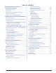
TABLE OF CONTENTS IMPORTANT SAFETY INFORMATION ..................... 3 CODES & REQUIREMENTS ..................................... 4 Combustion Air Quality............................................ 5 Heating Load ........................................................... 5 Operation of Furnace During Construction ............. 6 Installation in a Garage............................................ 6 Clearances to Combustible Materials...................... 6 COMBUSTION AIR & VENTING REQUIREMENTS .
FIGURES & TABLES ................................................. 33 Figure 31. *SL & *SM Cabinet Dimensions .......... 33 Figure 32. *SC & *SD Cabinet Dimensions.......... 34 Airflow Data ............................................................. 35 Table 6. *SC Upflow / Horizontal Furnaces .......... 35 Table 7. *SL Downflow Furnaces ......................... 36 Table 8. *SD Upflow / Horizontal Furnaces .......... 37 Table 9. *SM Downflow Furnaces ........................ 38 Electrical Information.........
s 4O MINIMIZE EQUIPMENT FAILURE OR PERSONAL INJURY IT IS essential that only qualified individuals install, service, or maintain this equipment. If you do not posses mechanical skills or tools, call your local dealer for assistance. s &OLLOW ALL PRECAUTIONS IN THE LITERATURE ON TAGS AND on labels provided with the equipment. Read and thoroughly understand the instructions provided with the equipment prior to performing the installation and operational checkout of the equipment.
2. For direct-vent appliances, mechanical-vent heating appliances or domestic hot water equipment where the bottom of the vent terminal and the air intake is installed above four feet above grade the following requirements must be satisfied: a.) A (CO) detector and alarm shall be placed on each floor level where there are bedrooms. The detector shall comply with NFPA 720 (2005 Edition) and be mounted in the living area outside the bedroom(s). b.
/PERATION OF &URNACE $URING #ONSTRUCTION Installation in a Garage WARNING: CAUTION: $O NOT PLACE COMBUSTIBLE MATERIAL ON OR AGAINST THE FURNACE CABINET OR WITHIN INCHES OF THE VENT PIPE $O NOT PLACE COMBUSTIBLE MATERIALS INCLUDING GASOLINE OR ANY OTHER mAMMABLE VAPORS AND LIQUIDS IN THE VICINITY OF THE FURNACE This gas-fired furnace may be installed in a residential garage with the provision that the burners and igniter are located no less than 18 inches (457mm) above the floor.
COMBUSTION AIR & VENTING REQUIREMENTS WARNING: CARBON MONOXIDE POISONING HAZARD &AILURE TO FOLLOW THE STEPS OUTLINED BELOW FOR EACH APPLIANCE CONNECTED TO THE VENTING SYSTEM BEING PLACED INTO OPERATION COULD RESULT IN CARBON MONOXIDE POISONING OR DEATH AVERTISSEMENT: 2)315% $ %-0/)3/..%-%.
)MPORTANT )NFORMATION s 4HIS FURNACE MUST BE VENTED IN COMPLIANCE WITH THE CURRENT REVISION OF THE .ATIONAL &UEL 'AS #ODE !.3) : .&0! )NSTRUCTIONS FOR DETERMINING THE ADEQUACY OF AN INSTALLATION CAN BE FOUND IN THE CURRENT REVISION OF THE .&'# !.3) : .&0! #ONSULT LOCAL CODES FOR SPECIAL REQUIREMENTS 4HESE REQUIREMENTS ARE FOR 53 INSTALLATIONS AS FOUND IN THE .&'# s &URNACE INSTALLATION USING METHODS OTHER THAN THOSE DESCRIBED IN THE FOLLOWING SECTIONS MUST COMPLY WITH THE .
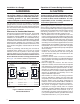
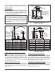
by the total input rate of all appliances in the space. In all cases, the minimum dimension of any combustion air opening is 3 inches. Vent or Chimney Ventilation Louvers (each end of attic) Air From Inside Outlet Air NOTE: Air openings shall each have a free area of not less than one square inch per 4,000 Btuh of the total input rating of all equipment in the enclosure.
Alternate Method of Providing Air from Outside Vent or Chimney Air Duct Water Heater Furnace Air Ducts must be at least 1 sq. in. per 2,000 Btuh of total input rating. Air Duct 4OTAL )NPUT 2ATING "TUH -INIMUM &REE !REA %ACH /PENING Round Duct $IAMETER 40,000 60,000 80,000 100,000 120,000 140,000 160,000 20 sq. In 30 sq. In 40 sq. In 50 sq. In 60 sq. In 70 sq. In 80 sq. In 5 inches 6 inches 7 inches 8 inches 9 inches 10 inches 10 inches Figure 5.
Category IV appliances operate with positive vent pressure and therefore require vent systems which are thoroughly sealed. They also produce liquid condensate, which is slightly acidic and can cause severe corrosion of ordinary venting materials. Furnace operation can be adversely affected by restrictive vent and combustion air piping. The inducer assembly on this furnace can be rotated to vent the flue products out of the top, left or right side.
Vent Pipe Installation CAUTION: #OMBUSTION AIR MUST NOT BE DRAWN FROM A CORROSIVE ATMOSPHERE This furnace has been certified for installation with zero clearance between vent piping and combustible surfaces. However, it is good practice to allow space for convenience in installation and service. s )N THE ABSENCE OF LOCAL CODES THE LOCATION OF ANY combustion air inlet relative to any vent terminal must be at least 8 inches. This includes installations involving more than one furnace.
s &OR OPTIMAL PERFORMANCE VENT THE FURNACE THROUGH A wall that experiences the least exposure to winter winds. s 4HE VENT TERMINATION SHALL BE LOCATED AT LEAST FT horizontally from any electric meter, gas meter, regulator and any relief equipment. These distances apply ONLY to U.S. installations. In Canada, CSA B149.1 takes precedence over these instructions.
Winter Design 4EMPERATURE -AXIMUM &LUE 0IPE ,ENGTH &%%4 IN 5NCONDITIONED %XTERIOR 3PACES 7ITHOUT )NSULATION 7ITH )NSULATION 20 45 70 0 20 70 -20 10 60 *NOTE: Insulation thickness greater than 3/8 inch, based on an R value of 3.5 (ft x F x hr) / (BTU x in.
and outdoor air is used, the ducts and damper system must be designed so that the return air supply to the furnace is equal to the return air supply under normal, indoor return air applications. s 7HEN A COOLING SYSTEM IS INSTALLED WHICH USES THE furnace blower to provide airflow over the indoor coil, the coil must be installed downstream (on the outlet side) of the furnace or in parallel with the furnace.
FURNACE INSTALLATION *SC & *SD series gas furnaces offer a wide range of installation options, including installation in the upflow or horizontal positions with either right, left, or upflow return air. *SL & *SM series gas furnaces may only be installed as a downflow application. 'ENERAL 2EQUIREMENTS s 4HE FURNACE MUST BE LEVELED AT INSTALLATION AND ATTACHED to a properly installed duct system.
WARNING: 3 &AILURE TO INSTALL THE DOWNmOW SUB BASE KIT MAY RESULT IN lRE PROPERTY DAMAGE OR PERSONAL INJURY To install an *SL & *SM series gas furnace on combustible flooring, a special sub-base is required. Downflow subbase kits are factory supplied accessories and are listed according to the cabinet letter of the furnace. For ‘B’, ‘C’, and ‘D’ size cabinets use Kit #904911. 0LEASE FOLLOW THE INSTRUCTIONS PROVIDED WITH THE KIT 1 2 Figure 13. 3# ! 0RESSURE 3WITCH 1.
)NDUCER 6ENTING /PTIONS Inducer Assembly Rotation To increase installation flexibility, the inducer assembly can be rotated up to 3 different positions. Each variation has slightly different requirements with regard to condensate disposal and, in some cases, the need to seal the furnace cabinet. )-0/24!.4 ./4% 4HE )NDUCER !SSEMBLY MUST NEVER BE POSITIONED TO VENT DOWNWARDS ON HORIZONTAL installs. Before using Table 4, the number of pipes (1-pipe or 2-pipe) connected to the furnace must be known.
Figure 15. 0RESSURE 3WITCH 4UBING FOR 3$ &URNACES /NLY Figure 16. 0RESSURE 3WITCH 4UBING FOR 5PmOW &URNACES -ODELS 3# 3# 3# 3# 3# -ODELS 3$ 3$ 3$ 3$ 3$ Figure 17.
1. Shut off any electrical power to the furnace. 2. Label and disconnect the tubing and wires from the pressure switch (Figure 18). 3. Remove two screws securing the pressure switch to the inducer housing. 4. Remove the pressure switch from the mounts on the inducer housing and relocate it to the other set of mounts 90° from previous location. 5. Secure the pressure switch with two screws. 6. Reconnect the tubes and wires to the pressure switch.
PVC Components Typical Orientation IMPORTANT NOTES: s "EFORE PERMANENTLY INSTALLING THESE COMPONENTS IT IS RECOMMENDED YOU DRY lT THEM lRST TO ENSURE PROPER lT AND ALIGNMENT WITH OTHER VENT PIPES s 4HE v 06# COMPONENTS SHOWN IN Figure 21 are not PROVIDED IN THE EXTRA PARTS BAG (OWEVER THE 06# 4RAP 0 . CAN BE PURCHASED THRU YOUR LOCAL DISTRIBUTOR 1. Install the PVC Tee vertically on the 2” vent pipe that is extending out the side of the cabinet.
2” x 3” PVC Coupling Coil Box 2” x 450 PVC Elbow 4. Carefully pull the blower assembly (4) out thru the front of the furnace. 5. Remove all screws (5) securing bottom panel (6) to bottom of furnace and front brace (7). 6. Lift up and slide bottom panel (6) out through front of furnace. 7. Reinstall the blower assembly (4) in reverse order. 2” PVC Pipe 1 3 2 Figure 22.
GAS SUPPLY & PIPING WARNING: FIRE OR EXPLOSION HAZARD s &AILURE TO FOLLOW SAFETY WARNINGS EXACTLY COULD RESULT IN SERIOUS INJURY OR PROPERTY DAMAGE s )NSTALLATION AND SERVICE MUST BE PERFORMED BY A QUALIlED INSTALLER SERVICE AGENCY OR THE GAS SUPPLIER s $O NOT STORE OR USE GASOLINE OR OTHER mAMMABLE VAPORS AND LIQUIDS IN THE VICINITY OF THIS OR ANY OTHER APPLIANCE WHAT TO DO IF YOU SMELL GAS s $O NOT TRY TO LIGHT ANY APPLIANCE s $O NOT TOUCH ANY ELECTRICAL SWITCH DO NOT USE ANY PHONE IN YOUR BUILDIN
AVERTISSEMENT: 2)315% $ ).$%.$)% /5 $ %80,/3)/. ,E NON RESPECT DES AVERTISSEMENTS DE SÏCURITÏ POURRAIT D ENTRAÔNER DES BLESSURES GRAVES LA MORT OU DES DOMMAGES MATÏRIELS .
*SC SERIES 2 6 2 6 1 See Note “A” See Note “A” 1 9 7 See Note “B” 9 See Note “B” 7 8 4 3 3 4 5 5 Right Side Entry Left Side Entry *SD SERIES 2 6 2 6 1 See Note “A” 9 See Note “A” 1 See Note “B” See Note “B” 7 9 7 8 3 3 4 4 5 Left Side Entry 5 Right Side Entry (1) Automatic Gas Valve (w/ manual shut-off) (2) Burner Assembly (3) Dripleg (4) Elbow (5) Ground Joint Union (6) Manifold (7) Pipe Nipple (8) Plug (9) Shut - Off Valve NOTE A: Consult local codes for Shut-
#ONVERTING FROM .ATURAL 'AS TO ,0 0ROPANE WARNING: 4HE FURNACE WAS SHIPPED FROM THE FACTORY EQUIPPED TO OPERATE ON NATURAL GAS #ONVERSION TO ,0 0ROPANE GAS MUST BE PERFORMED BY QUALIlED SERVICE PERSONNEL USING A FACTORY SUPPLIED CONVERSION KIT &AILURE TO USE THE PROPER CONVERSION KIT CAN CAUSE lRE EXPLOSION PROPERTY DAMAGE CARBON MONOXIDE POISONING PERSONAL INJURY OR DEATH Conversion to LP / Propane is detailed in the installation instructions provided with the conversion kit.
Line Voltage Wiring It is recommended that the line voltage (115 VAC) to the furnace be supplied from a dedicated branch circuit containing the correct fuse or circuit breaker for the furnace as listed in Table 17.
4HERMOSTAT ,OW 6OLTAGE #ONNECTIONS Twinning s 4HE FURNACE IS DESIGNED TO BE CONTROLLED BY A 6!# thermostat. The thermostat’s wiring must comply with the current provisions of the NEC (ANSI/NFPA 70) and with applicable local codes having jurisdiction. s 4HE THERMOSTAT MUST BE INSTALLED ACCORDING TO THE instructions supplied by the thermostat manufacturer. Low voltage connections (24 VAC) from the thermostat are wired to the terminal strip on the integrated control in the furnace.
THERMOSTAT W G Y R Expansion Port Expansion Port R C Y G W R C Y G W FURNACE BOARD FURNACE BOARD A/C UNIT FURNACE 2 FURNACE 1 6-Pin Wiring Harness 6-Pin Wiring Harness Expansion Port Expansion Port TWINNING CONTROL BOARD TWIN TERMINAL TWINNING CONTROL BOARD TWIN TERMINAL Figure 29. Single Stage Twinning 34!24 50 !$*534-%.43 0RE 3TART #HECK ,IST Verify the polarity of the connections are correct, the line voltage power leads are securely connected and the furnace is properly grounded.
screw all the way out from the valve, turn the screw slowly. d.) Replace and tighten the regulator capscrew over the adjustment screw. 6ERIFYING !DJUSTING 4EMPERATURE 2ISE After installation of the furnace, confirm the temperature rise of the furnace is within the limits specified on the rating plate. Any temperature rise outside the specified limits could result in premature failure of the heat exchanger. 1. Place thermometers in the return and supply air stream as close to the furnace as possible.
indoor fan is energized on the selected FAN speed. s )F A CALL FOR COOLING OCCURS DURING CONTINUOUS FAN THE blower will switch over to the selected COOL speed. s )F THE W terminal receives a call for heat during continuous fan, the blower will de energize. s ! CALL FOR FAN IS IGNORED WHILE IN LOCKOUT MAINTENANCE Proper maintenance is most important to achieve the best performance from a furnace. Follow these instructions for years of safe, trouble free operation.
6. Using two wrenches, separate the ground-joint union in the gas supply piping at the furnace. 7. Remove the piping between the Gas Valve and the ground-joint union. (If applicable). 8. Remove all screws securing the Manifold Assembly to the Burner Box. 9. Carefully remove the burner assembly from the furnace. DO NOT DAMAGE THE IGNITER WHILE REMOVING THE BURNER ASSEMBLY. 10.Inspect the burners for accumulated dust or debris. If necessary carefully clean them with a soft wire brush and a vacuum cleaner.
TOP VIEW 3# 5PmOW (ORIZONTAL &URNACES $IM ! $IM " $IM # 038D-23A 14 1/4 12 5/8 12 7/8 17 1/2 15 7/8 16 1/8 054D-24B 072D-24B 072D-35C 090D-35C 108D-45D 120D-45D 21 19 3/8 C Front Brace FL AN 19 GE S 23 1/2 -ODEL S BOTTOM VIEW B 19 5/8 Bottom Panel Flue 24 1/2 22 7/8 Combustion Air 23 1/8 3 1/4 3 NOTE: Dimensions shown in inches.
Airflow Data -!8)-5- !)2&,/7 4%-0%2!452% 2)3%3 0 & &/2 3# 3%2)%3 50&,/7 (/2):/.4!, &52.!#%3 -ODEL .
-!8)-5- !)2&,/7 4%-0%2!452% 2)3%3 0 & &/2 3# 3%2)%3 50&,/7 (/2):/.4!, &52.!#%3 %XTERNAL 3TATIC 0RESSURE )NCHES 7ATER #OLUMN -ODEL .UMBER & (EATING )NPUT "TUH SC108D-45D Bottom only or 2 openings (108,000) SC108D-45D Side Return (108,000) SC120D-45D Bottom only or 2 openings (120,000) SC120D-45D Side Return (120,000) Motor 3PEED 0.1 CFM 2,135 High* Med-High** 2,000 0.2 0.3 0.4 0.5 0.6 0.7 0.
-!8)-5- !)2&,/7 4%-0%2!452% 2)3%3 0 & &/2 3$ 3%2)%3 50&,/7 (/2):/.4!, &52.!#%3 -ODEL .
-!8)-5- !)2&,/7 4%-0%2!452% 2)3%3 0 & &/2 50&,/7 (/2):/.4!, &52.!#%3 3$ 3%2)%3 -ODEL .UMBER & (EATING )NPUT "TUH SD108D-45D Bottom Return (108,000) SD108D-45D Side Return (108,000) SD120D-45D Bottom Return (120,000) SD120D-45D Side Return (120,000) %XTERNAL 3TATIC 0RESSURE )NCHES 7ATER #OLUMN Motor 3PEED 0.1 0.2 0.3 0.4 0.5 0.6 0.7 0.
Yellow LED Continuous Flash On WHITE (NEUTRAL) BLACK 120V GROUND GREEN BLACK BLACK 1 4 3 2 1 7 6 5 4 2 5 8 BLACK 3 6 9 WHITE BLACK WHITE RED GREY 24V L1A DOOR SWITCH BLACK HUM LEGEND: 1 1 2 2 BLACK BLACK YELLOW 24 V BK/WH STRIPE 3 AMP FUSE COM 1 2 3 4 1 2 3 4 ORANGE ORANGE WH/BK STRIPE PRESSURE SWITCH (ON SELECT MODELS) ORANGE BLUE/WHITE BLACK 120 V WHITE PRESSURE SWITCH 1 YELLOW GREEN RED VENT LIMIT SWITCH XFMR FIELD WIRING LOW VOLTAGE HIGH VOLTAGE C INDUCER R
'AS )NFORMATION GAS FLOW RATES #5")# &%%4 0%2 (/52 TIME FOR ONE REVOLUTION 3%#/.$3 GAS FLOW RATES #5")# &%%4 0%2 (/52 CUBIC FEET PER REVOLUTION OF GAS METER CUBIC FEET PER REVOLUTION OF GAS METER 1 5 10 TIME FOR ONE REVOLUTION 3%#/.
()'( !,4)45$% $%2!4)/. n 02/0!.% '!3 ALTITUDE ABOVE SEA LEVEL 0 to 1,999 FT 2,000 to 2,999 FT 3,000 to 4,999 FT 5,000 to 5,999 FT 6,000 to 7,999 FT 8,000 to 10,000 FT ).054 "45 3# -ODELS 3$ -ODELS 56 60 56 56 56 56 55 55 10.0 10.0 10.0 10.0 10.0 10.0 10.0 10.0 ORIFICE SIZE MANIFOLD PRESSURE 56 60 56 56 56 56 55 55 ORIFICE SIZE 9.0 9.0 9.0 9.0 9.0 9.0 9.0 9.
()'( !,4)45$% $%2!4)/. n .!452!, '!3 7)4( ()'( (%!4).' 6!,5% ALTITUDE ABOVE SEA LEVEL TO &4 TO &4 TO &4 TO &4 TO &4 TO &4 TO &4 TO &4 TO &4 ).054 "45 3# -ODELS 3$ -ODELS 45 51 47 47 47 47 46 45 ORIFICE SIZE 3.5 3.5 3.5 3.5 3.5 3.5 3.5 3.5 MANIFOLD PRESSURE 45 51 47 47 47 47 46 45 ORIFICE SIZE 3.0 3.2 3.
6ENTING )NFORMATION AIR SUPPLY INLET VENT TERMINAL AREA WHERE TERMINAL IS NOT PERMITTED CANADIAN INSTALLATIONS a US INSTALLATIONS B $IRECT 6ENT PIPE #ONVENTIONAL 6ENT PIPE Furnaces Direct Vent PIPE &URNACES #ONVENTIONAL 6ENT PIPE &URNACES 12 inches (30cm) 12 inches (30cm) 12 inches (30cm) 6 inches (15cm) for appliances < 10,000 Btuh (3kW) 6 inches (15cm) for appliances < 10,000 Btuh (3kW) 12 inches (30cm) for appliances 10,000 Btuh - 100,000 Btuh (30kW) 9 inches (23cm) for app
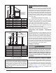
3# 3, 3ERIES !&5% HORIZONTAL VENTING w/ 2-Pipes Straps or other suitable supports at minimum 5 ft. intervals (both pipes) (Upflow Furnace Shown) Wall First support as close to furnace as possible 90° Elbows Seal / caulk around pipes at wall 90° Elbow COMBUSTION AIR VENT PIPE FLUE PIPE Rubber Grommet Flue Pipe must slope upward 1/4” per foot 7” 12” Min.
3$ 3- 3ERIES !&5% HORIZONTAL VENTING w/ 2-Pipes Straps or Other Suitable Supports at minimum of 5 ft. Intervals (Upflow Furnace Shown) Seal/Caulk Around Pipes at Building 90° Elbow 90° Elbow COMBUSTION AIR See Table 2 for 2” PVC pipe lengths (field supplied) Upward Pitch - 1/4” per foot (Flue Pipe) FLUE PIPE Coupling with 2 Hose Clamps (Optional) 90° Elbow First support placed as close to furnace connection as possible 12” Min.
95.
95.0% HORIZONTAL LEFT - 1 PIPE OPTION Rubber Grommet Option 26 FLUE PIPE Option 25 FLUE PIPE 95.0% HORIZONTAL RIGHT - 1 PIPE OPTION Rubber Grommet COMBUSTION AIR COMBUSTION AIR See VIEW Q for drain line positions See VIEW R for drain line positions Plug Plug Inline Drain (Factory Supplied) See NOTE 3 VIEW -Q- VIEW -RInline Drain (Factory Supplied) See NOTE 2 Collector Box Drain (Factory Equipped) See NOTE 2 Collector Box Drain (Factory Equipped) See NOTE 2 NOTES: 1.
TROUBLESHOOTING )F THE FURNACE FAILS TO OPERATE CHECK THE FOLLOWING s )S THE THERMOSTAT OPERATING PROPERLY s !RE THE BLOWER COMPARTMENT DOOR S IN PLACE s )S THE FURNACE DISCONNECT CLOSED s (AS THE CIRCUIT BREAKER TRIPPED OR THE CONTROL BOARD FUSE BURNED OPEN s )S THE GAS TURNED ON s !RE ANY MANUAL RESET SWITCHES OPEN s )S THE lLTER DIRTY OR PLUGGED s )S THE mAME SENSOR COATED 2EMOVE AND CLEAN WITH steel wool.
Flame Sensor Finish Igniter Flange Roll-Out Burner Switch Assembly Gas Manifold Control Board Main Air Limit Switch Gas Valve Vent Limit Switch Pressure Switch - Condensate (‘B’, ‘C’, & ‘D’ cabinets only) Transformer Inducer Assembly Pressure Switch (Inducer) Blower Door Switch Blower Assembly 3# 3ERIES 5PmOW (ORIZONTAL &URNACE Finish Flange Flame Sensor Roll-Out Switch Burner Assembly Igniter Main Air Limit Switch Inducer Limit Switch Pressure Switch (Inducer) Inducer Assembly Blower Door Swit
).34!,,!4)/. 0%2&/2-!.#% #(%#+ ,)34 ELECTRICAL SYSTEM ATTENTION INSTALLERS: It is your responsibility to know this product better than your customer. This includes being able to install the product according to strict safety guidelines and instructing the customer on how to operate and maintain the equipment for the life of the product. Safety should always be the deciding factor when installing this product and using common sense plays an important role as well.