
Installation Guide


29
4HERMOSTAT,OW6OLTAGE#ONNECTIONS
s 4HEFURNACEISDESIGNEDTOBECONTROLLEDBYA6!#
thermostat. The thermostat’s wiring must comply with
the current provisions of the NEC (ANSI/NFPA 70) and
with applicable local codes having jurisdiction.
s 4HE THERMOSTAT MUST BE INSTALLED ACCORDING TO THE
instructions supplied by the thermostat manufacturer.
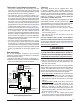
Low voltage connections (24 VAC) from the thermostat
are wired to the terminal strip on the integrated control in
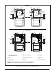
the furnace. Figure 28 contains the proper connections
for heating only (two-wire) and heating/cooling (four-
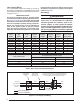
wire) applications. Recommended minimum wire gauge
for thermostat wiring is shown in Table 5 (page 28).
s 4HETHERMOSTATSHOULDBEMOUNTEDABOUTFEETABOVE
the floor on an inside wall. DO NOT install the thermostat
on an outside wall or any other location where its
operation may be adversely affected by radiant heat from
fireplaces, sunlight, or lighting fixtures, and convective
heat from warm air registers or electrical appliances.
Refer to the thermostat manufacturer’s instruction sheet
for detailed mounting information.
s 4HESIXPINTERMINALMARKEDh%XPANSION0ORTvFigure
28) is not used in the single stage furnace as shipped
from the factory. It is used for the furnace control board
to communicate to a fixed speed or variable speed high
efficiency motor that may be optionally installed. Please
contact your distributor for the proper upgrade motor
kit.
(EAT!NTICIPATOR
Set the heat anticipator according to the instructions
supplied by the thermostat manufacturer. To determine
the heat anticipator setting:
1. Add the current draw of the system components; or
2. Measure the current flow on the thermostat R-W circuit
after the circulating blower motor has started.
Twinning
Single stage furnaces are not supplied with a built-
in twinning capability. Other valuable features and
enhancements were made to the new control that made it
necessary to remove the twinning capability. For twinning
of single stage furnaces with PSC motors, a twinning kit
(920919) is available for purchase. 0LEASEFOLLOWTHE
INSTRUCTIONSPROVIDEDWITHTHEKIT
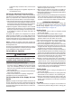
If both single stage furnaces are upgraded to the fixed
speed iSEER™ blower, the twin terminal on the blower
control boards (Figure 29) may be used to twin the single
stage furnaces only if the following criteria are met:
s "OTHFURNACESANDMOTORSMUSTBETHESAMESIZE
s "OTHMOTORSMUSTBEONTHESAMESPEEDFORCOOLING
and heating.
s "OTHFURNACESMUSTHAVEACOMMONRETURNDUCTAND
common supply plenum.
s "OTH FURNACES MUST BE THE SAME PHASE AND ON THE
same leg of power.
&URNACES EQUIPPED WITH VARIABLE SPEED I3%%2
MOTORSMAYNOTBETWINNEDUNDERANYCIRCUMSTANCES
For twinning of single stage furnaces equipped with fixed
speed iSEER™ blowers, refer to Figure 29 (page 30)
and the following instructions:
WARNING:
7HENSERVICINGEITHERTWINNEDFURNACEPOWER
MUSTBETURNEDOFFONBOTHFURNACES&AILURETO
COMPLYMAYRESULTINIMPROPEROPERATIONLEADING
TODAMAGETOTHEFURNACESORPERSONALINJURY
1. Turn off all power to both furnaces.
2. Attach a wire between the two twin terminals on the
twinning control boards. Use field supplied wire and
two 3/16” wire terminals.
NOTE: One furnace can be used for one stage of heating
and the other furnace can be used for the second stage of
heating. The installer also has the choice of running one
furnace only or both furnaces. In both cases the blowers
will run at the same time and at the same speeds:
s Single stage heating: The W connection on each furnace
must be connected together and then connected to
the W connection of the thermostat. This will allow
both furnaces to ignite at the same time for one stage
heating.
s Two stage heating: The W connection on one furnace
must be connected to the W1 connection of the
thermostat. The W connection of the second furnace
must be connected to the W2 connection of the
thermostat. This will allow one furnace to ignite for one
stage of heating and the second furnace to ignite for
the second stage of heating.
3.Refer to Figure 29 for the remaining thermostat
connections. The C connection must be made between
the twinned furnaces to ensure proper performance.
Figure 28.
,OW6OLTAGE&IELD&OURWIRE
(EATING#OOLING!PPLICATIONS
RCYGW
STATUS
FLAME
GREEN
RED
180
COOL
HEAT
120
90
60
YELLOW
BLOWER
OFF
DELAY
LOW
ML
MH
HIGH
EAC
L1
XFMR
HUM
COM
SPEED
SELECT
3 AMP
FUSE
24V
5
NEUTRALS
ROOM
THERMOSTAT
A/C CONDENSING UNIT
CONDENSING UNIT
CONTROL BOX
EXPANSION PORT
(MOTOR CONNECTION)
FIELD WIRING
LOW VOLTAGE
CONNECTION
R
C
Y
G
W
NOTE: The “Y” terminal
on the control board
must be connected to the
thermostat for proper
cooling mode operation.
Connect
R & W
For Heating
Only
2
ELECTRONIC AIR CLEANER
MOTOR SPEED TAPS
(NOT USED)
HUMIDIFIER TAP
NEUTRAL LEADS
63
4
1
7
8
9
5
2
63
4
1
FAN