
Installation Guide


33
6. Using two wrenches, separate the ground-joint union
in the gas supply piping at the furnace.
7. Remove the piping between the Gas Valve and the
ground-joint union. (If applicable).
8. Remove all screws securing the Manifold Assembly to
the Burner Box.
9. Carefully remove the burner assembly from the furnace.
DO NOT DAMAGE THE IGNITER WHILE REMOVING
THE BURNER ASSEMBLY.
10.Inspect the burners for accumulated dust or debris.
If necessary carefully clean them with a soft wire
brush and a vacuum cleaner. DO NOT DAMAGE THE
IGNITER WHILE CLEANING THE BURNER.
11.Replace all the parts in reverse order from which they
were removed.
12.Follow the lighting instructions found on the furnace
door to return the furnace to operation. Verify proper
operation after servicing.
6ENT3YSTEM Check the inlet pipe (if applicable) and
outlet pipe to ensure they are not blocked by debris. Any
damaged section of vent pipe must be replaced, and
any obstruction or blockage must be removed prior to
operating the furnace.
(EAT%XCHANGER"URNER-AINTENANCE The furnace
should operate for many years without soot buildup in the
flue passageways, however, the flue, vent system, and
burners should be inspected and cleaned (if required) by
a qualified service technician annually to ensure continued
safe operation. Pay attention to any deterioration from
corrosion or other sources.
WARNING:
(OLESINTHEVENTPIPEORHEATEXCHANGERCAN
CAUSECOMBUSTIONPRODUCTSTOENTERTHEHOME
2EPLACETHEVENTPIPEORHEATEXCHANGERIFLEAKS
ARE FOUND &AILURE TO PREVENT THE CIRCULATION
OFCOMBUSTIONPRODUCTSINTOTHELIVINGSPACE
CAN CREATE POTENTIALLY HAZARDOUS CONDITIONS
INCLUDING CARBON MONOXIDE POISONING THAT
COULDRESULTINPERSONALINJURYORDEATH
,UBRICATION The bearings in the blower motor and
inducer blower used in these furnaces are pre-lubricated
and sealed by the manufacturer. No further oiling of the
bearings is required for the life of the motor.
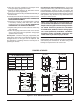
FIGURES & TABLES
A
34 1/2
17 1/4
10 1/4
22 1/4
22 1/2
2 3/4
22 1/2
22 1/4
25
17 7/16
29 1/2
17 1/4
22 1/2
25 3/8
Gas
(Ø 1 5/8)
T-stat
(Ø 7/8)
18 1/2
Front
Brace
LEFT SIDE
RIGHT SIDE
Electric
(Ø 7/8)
25 1/2
22 1/2
Gas (Ø 1 5/8)
Vent pipe
(Ø 3”)
Cond. (Ø 1 1/16)
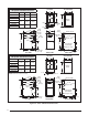
B
19
FLANGES
TOP VIEW
C
BOTTOM VIEW
Electric
(Ø 7/8)
Vent pipe
(Ø 3”)
Cond. (Ø 1 1/16)
FRONT VIEW
28
3
Flue
Combustion
Air
7 1/2
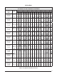
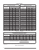
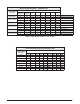
*SL & *SM Downflow Furnaces
-ODELS $IM! $IM" $IM#
054D-24B
17 1/2 15 7/8 16 1/8
072D-24B
072D-35C
21 19 3/8 19 5/8
090D-35C
118D-45D
24 1/2 22 7/8 23 1/8
120D-45D
NOTE: Dimensions shown in inches.
Figure 31. 3,3-#ABINET$IMENSIONS