Single Stage Condensing Gas Furnaces 92.1% & 95.0% AFUE INSTALLATION INSTRUCTIONS *SC Upflow / Horizontal Model *SD Upflow / Horizontal Models WARNING: FIRE OR EXPLOSION HAZARD • Failure to follow safety warnings exactly could result in serious injury or property damage. • Installation and service must be performed by a qualified installer, service agency or the gas supplier. • Do not store or use gasoline or other flammable vapors and liquids in the vicinity of this or any other appliance.
TABLE OF CONTENTS IMPORTANT SAFETY INFORMATION...................... 3 CODES & REQUIREMENTS...................................... 4 Combustion Air Quality............................................ 5 Heating Load............................................................ 5 Operation of Furnace During Construction.............. 6 Installation in a Garage............................................ 6 Clearances to Combustible Materials...................... 6 COMBUSTION AIR & VENTING REQUIREMENTS ..
FIGURES & TABLES.................................................. 33 Figure 31. *SL & *SM Cabinet Dimensions........... 33 Figure 32. *SC & *SD Cabinet Dimensions........... 34 Airflow Data.............................................................. 35 Table 6. *SC Upflow / Horizontal Furnaces........... 35 Table 7. *SL Downflow Furnaces.......................... 36 Table 8. *SD Upflow / Horizontal Furnaces........... 37 Table 9. *SM Downflow Furnaces......................... 38 Electrical Information...
• To minimize equipment failure or personal injury, it is essential that only qualified individuals install, service, or maintain this equipment. If you do not posses mechanical skills or tools, call your local dealer for assistance. • Follow all precautions in the literature, on tags, and on labels provided with the equipment. Read and thoroughly understand the instructions provided with the equipment prior to performing the installation and operational checkout of the equipment.
2. For direct-vent appliances, mechanical-vent heating appliances or domestic hot water equipment where the bottom of the vent terminal and the air intake is installed above four feet above grade the following requirements must be satisfied: a.) A (CO) detector and alarm shall be placed on each floor level where there are bedrooms. The detector shall comply with NFPA 720 (2005 Edition) and be mounted in the living area outside the bedroom(s). b.
Installation in a Garage Operation of Furnace During Construction WARNING: CAUTION: Do not place combustible material on or against the furnace cabinet or within 6 inches of the vent pipe. Do not place combustible materials, including gasoline or any other flammable vapors and liquids, in the vicinity of the furnace. This gas-fired furnace may be installed in a residential garage with the provision that the burners and igniter are located no less than 18 inches (457mm) above the floor.
COMBUSTION AIR & VENTING REQUIREMENTS WARNING: CARBON MONOXIDE POISONING HAZARD Failure to follow the steps outlined below for each appliance connected to the venting system being placed into operation could result in carbon monoxide poisoning or death.
Important Information • This furnace must be vented in compliance with the current revision of the National Fuel Gas Code (ANSI-Z223.1/NFPA54). Instructions for determining the adequacy of an installation can be found in the current revision of the NFGC (ANSI Z223.1 / NFPA54). Consult local codes for special requirements. These requirements are for US installations as found in the NFGC.
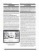
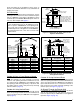
by the total input rate of all appliances in the space. In all cases, the minimum dimension of any combustion air opening is 3 inches. Vent or Chimney Ventilation Louvers (each end of attic) Air From Inside Outlet Air NOTE: Air openings shall each have a free area of not less than one square inch per 4,000 Btuh of the total input rating of all equipment in the enclosure.
Alternate Method of Providing Air from Outside Vent or Chimney Air Duct Water Heater Furnace Air Ducts must be at least 1 sq. in. per 2,000 Btuh of total input rating. Air Duct Total Input Rating (Btuh) Minimum Free Area (Each Opening) Round Duct Diameter 40,000 60,000 80,000 100,000 120,000 140,000 160,000 20 sq. In 30 sq. In 40 sq. In 50 sq. In 60 sq. In 70 sq. In 80 sq. In 5 inches 6 inches 7 inches 8 inches 9 inches 10 inches 10 inches Figure 5.
Category IV appliances operate with positive vent pressure and therefore require vent systems which are thoroughly sealed. They also produce liquid condensate, which is slightly acidic and can cause severe corrosion of ordinary venting materials. Furnace operation can be adversely affected by restrictive vent and combustion air piping. The inducer assembly on this furnace can be rotated to vent the flue products out of the top, left or right side.
Vent Pipe Installation CAUTION: Combustion air must not be drawn from a corrosive atmosphere. This furnace has been certified for installation with zero clearance between vent piping and combustible surfaces. However, it is good practice to allow space for convenience in installation and service. • In the absence of local codes, the location of any combustion air inlet relative to any vent terminal must be at least 8 inches. This includes installations involving more than one furnace.
• For optimal performance, vent the furnace through a wall that experiences the least exposure to winter winds. • The vent termination shall be located at least 3 ft. horizontally from any electric meter, gas meter, regulator and any relief equipment. These distances apply ONLY to U.S. installations. In Canada, CSA B149.1 takes precedence over these instructions.
Winter Design Temperature Maximum Flue Pipe Length (FEET) in Unconditioned & Exterior Spaces Without Insulation With Insulation* 20 45 70 0 20 70 -20 10 60 *NOTE: Insulation thickness greater than 3/8 inch, based on an R value of 3.5 (ft x F x hr) / (BTU x in.) Table 2.
and outdoor air is used, the ducts and damper system must be designed so that the return air supply to the furnace is equal to the return air supply under normal, indoor return air applications. • When a cooling system is installed which uses the furnace blower to provide airflow over the indoor coil, the coil must be installed downstream (on the outlet side) of the furnace or in parallel with the furnace.
FURNACE INSTALLATION *SC & *SD series gas furnaces offer a wide range of installation options, including installation in the upflow or horizontal positions with either right, left, or upflow return air. *SL & *SM series gas furnaces may only be installed as a downflow application. General Requirements • The furnace must be leveled at installation and attached to a properly installed duct system.
WARNING: 3 Failure to install the downflow sub-base kit may result in fire, property damage or personal injury. To install an *SL & *SM series gas furnace on combustible flooring, a special sub-base is required. Downflow subbase kits are factory supplied accessories and are listed according to the cabinet letter of the furnace. For ‘B’, ‘C’, and ‘D’ size cabinets use Kit #904911. Please follow the instructions provided with the kit. 1 2 Figure 13. SC038-23A Pressure Switch 1.
Inducer & Venting Options To increase installation flexibility, the inducer assembly can be rotated up to 3 different positions. Each variation has slightly different requirements with regard to condensate disposal and, in some cases, the need to seal the furnace cabinet. IMPORTANT NOTE: The Inducer Assembly must never be positioned to vent downwards on horizontal installs. Before using Table 4, the number of pipes (1-pipe or 2-pipe) connected to the furnace must be known.
Figure 15. Pressure Switch Tubing for *SD038 Furnaces Only Figure 16. Pressure Switch Tubing for Upflow Furnaces (Models *SC054, *SC072, *SC090, *SC108, & *SC120) (Models *SD054, *SD072, *SD090, *SD108, & *SD120) Figure 17.
1. Shut off any electrical power to the furnace. 2. Label and disconnect the tubing and wires from the pressure switch (Figure 18). 3. Remove two screws securing the pressure switch to the inducer housing. 4. Remove the pressure switch from the mounts on the inducer housing and relocate it to the other set of mounts 90° from previous location. 5. Secure the pressure switch with two screws. 6. Reconnect the tubes and wires to the pressure switch.
PVC Components Typical Orientation IMPORTANT NOTES: • Before permanently installing these components, it is recommended you dry-fit them first to ensure proper fit and alignment with other vent pipes. • The 2” PVC components shown in Figure 21 are not provided in the extra parts bag. However the PVC Trap (P/N 664659) can be purchased thru your local distributor. 1. Install the PVC Tee vertically on the 2” vent pipe that is extending out the side of the cabinet.
2” x 3” PVC Coupling Coil Box 2” x 450 PVC Elbow 4. Carefully pull the blower assembly (4) out thru the front of the furnace. 5. Remove all screws (5) securing bottom panel (6) to bottom of furnace and front brace (7). 6. Lift up and slide bottom panel (6) out through front of furnace. 7. Reinstall the blower assembly (4) in reverse order. 2” PVC Pipe 1 3 2 Figure 22.
GAS SUPPLY & PIPING WARNING: FIRE OR EXPLOSION HAZARD • Failure to follow safety warnings exactly could result in serious injury or property damage. • Installation and service must be performed by a qualified installer, service agency or the gas supplier. • Do not store or use gasoline or other flammable vapors and liquids in the vicinity of this or any other appliance. WHAT TO DO IF YOU SMELL GAS • Do not try to light any appliance.
AVERTISSEMENT: RISQUE D’INDENDIE OU D’EXPLOSION Le non-respect des avertissements de sécurité pourrait d’entraîner des blessures graves, la mort ou des dommages matériels. Ne jamais utiliser une flamme nue por vérifier la présence des fuites de gaz. Pour la vérification de tous les joints, utiliser plutôt une solution savonneuse commerciale fabriquée spécifiquement pur la détection des fuites de gaz. Un incendie ou une explosion peut entraîner des dommages matériels, des blessures ou la mort.
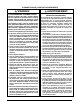
*SC SERIES 2 6 2 6 1 See Note “A” See Note “A” 1 9 7 See Note “B” 9 See Note “B” 7 8 4 3 3 4 5 5 Right Side Entry Left Side Entry *SD SERIES 2 6 2 6 1 See Note “A” 9 See Note “A” 1 See Note “B” See Note “B” 7 9 7 8 3 3 4 4 5 Left Side Entry 5 Right Side Entry (1) Automatic Gas Valve (w/ manual shut-off) (2) Burner Assembly (3) Dripleg (4) Elbow (5) Ground Joint Union (6) Manifold (7) Pipe Nipple (8) Plug (9) Shut - Off Valve NOTE A: Consult local codes for Shut
*SL SERIES See Note “A” See Note “A” See Note “B” 9 See Note “B” 4 9 4 8 3 5 3 7 5 7 1 Left Side Entry 2 Right Side Entry 6 2 2 6 *SM SERIES See Note “A” See Note “A” 9 9 4 4 8 3 See Note “B” 5 See Note “B” 7 7 1 2 Left Side Entry 6 5 1 2 Right Side Entry 6 (1) Automatic Gas Valve (w/ manual shut-off) (2) Burner Assembly (3) Dripleg (4) Elbow (5) Ground Joint Union (6) Manifold (7) Pipe Nipple (8) Plug (9) Shut - Off Valve NOTE A: Consult local codes for S
Converting from Natural Gas to LP / Propane WARNING: The furnace was shipped from the factory equipped to operate on natural gas. Conversion to LP / Propane gas must be performed by qualified service personnel using a factory supplied conversion kit. Failure to use the proper conversion kit can cause fire, explosion, property damage, carbon monoxide poisoning, personal injury, or death. Conversion to LP / Propane is detailed in the installation instructions provided with the conversion kit.
Line Voltage Wiring It is recommended that the line voltage (115 VAC) to the furnace be supplied from a dedicated branch circuit containing the correct fuse or circuit breaker for the furnace as listed in Table 17. IMPORTANT NOTES: An electrical disconnect must be installed readily accessible from and located within sight of the furnace. See Figure 27 (page 28) or the wiring diagram label inside of the control door. Any other wiring methods must be acceptable to authority having jurisdiction.
Thermostat / Low Voltage Connections • The furnace is designed to be controlled by a 24 VAC thermostat. The thermostat’s wiring must comply with the current provisions of the NEC (ANSI/NFPA 70) and with applicable local codes having jurisdiction. • The thermostat must be installed according to the instructions supplied by the thermostat manufacturer. Low voltage connections (24 VAC) from the thermostat are wired to the terminal strip on the integrated control in the furnace.
THERMOSTAT W G Y R Expansion Port Expansion Port R C Y G W R C Y G W FURNACE BOARD FURNACE BOARD A/C UNIT FURNACE 2 FURNACE 1 6-Pin Wiring Harness 6-Pin Wiring Harness Expansion Port Expansion Port TWINNING CONTROL BOARD TWIN TERMINAL TWINNING CONTROL BOARD TWIN TERMINAL Figure 29. Single Stage Twinning START-UP & ADJUSTMENTS Pre-Start Check List √ Verify the polarity of the connections are correct, the line voltage power leads are securely connected and the furnace is properly grounded.
screw all the way out from the valve, turn the screw slowly. d.) Replace and tighten the regulator capscrew over the adjustment screw. Verifying & Adjusting Temperature Rise After installation of the furnace, confirm the temperature rise of the furnace is within the limits specified on the rating plate. Any temperature rise outside the specified limits could result in premature failure of the heat exchanger. 1. Place thermometers in the return and supply air stream as close to the furnace as possible.
indoor fan is energized on the selected FAN speed. • If a call for cooling occurs during continuous fan, the blower will switch over to the selected COOL speed. • If the W terminal receives a call for heat during continuous fan, the blower will de energize. • A call for fan is ignored while in lockout. MAINTENANCE Proper maintenance is most important to achieve the best performance from a furnace. Follow these instructions for years of safe, trouble free operation.
6. Using two wrenches, separate the ground-joint union in the gas supply piping at the furnace. 7. Remove the piping between the Gas Valve and the ground-joint union. (If applicable). 8. Remove all screws securing the Manifold Assembly to the Burner Box. 9. Carefully remove the burner assembly from the furnace. DO NOT DAMAGE THE IGNITER WHILE REMOVING THE BURNER ASSEMBLY. 10.Inspect the burners for accumulated dust or debris. If necessary carefully clean them with a soft wire brush and a vacuum cleaner.
TOP VIEW *SC Upflow / Horizontal Furnaces Dim. -A- Dim. -B- Dim. -C- 038D-23A 14 1/4 12 5/8 12 7/8 17 1/2 15 7/8 16 1/8 21 19 3/8 19 5/8 054D-24B 072D-24B 072D-35C 090D-35C 108D-45D 120D-45D C Front Brace FL AN GE S Flue 24 1/2 22 7/8 23 1/8 3 1/4 NOTE: Dimensions shown in inches.
Airflow Data MAXIMUM AIRFLOW & TEMPERATURE RISES (0 F) FOR *SC SERIES UPFLOW / HORIZONTAL FURNACES Model Number & Heating Input (Btuh) SC038D-23A Bottom Return (38,000) SC038D-23A Side Return (38,000) SC054D-24B Bottom Return (54,000) SC054D-24B Side Return (54,000) SC072D-24B Bottom Return (72,000) SC072D-24B Side Return (72,000) SC072D-35C Bottom Return (72,000) SC072D-35C Side Return (72,000) SC072D-35C Side + Bottom or 2 Sides (72,000) SC090D-35C Bottom Return (90,000) SC090D-35C Side Return (
MAXIMUM AIRFLOW & TEMPERATURE RISES (0 F) FOR *SC SERIES UPFLOW / HORIZONTAL FURNACES External Static Pressure (Inches Water Column) Model Number & Heating Input (Btuh) SC108D-45D Bottom only or 2 openings (108,000) SC108D-45D Side Return (108,000) SC120D-45D Bottom only or 2 openings (120,000) SC120D-45D Side Return (120,000) Motor Speed 0.1 CFM 2,135 High* Med-High** 2,000 0.2 0.3 0.4 0.5 0.6 0.7 0.
MAXIMUM AIRFLOW & TEMPERATURE RISES (0 F) FOR *SD SERIES UPFLOW / HORIZONTAL FURNACES Model Number & Heating Input (Btuh) SD038D-24B Bottom Return (38,000) SD038D-24B Side Return (38,000) SD054D-24B Bottom Return (54,000) SD054D-24B Side Return (54,000) SD072D-35C Bottom Return (72,000) SD072D-35C Side Return (72,000) SD72D-35C Side + Bottom or 2 Sides (72,000) SD090D-35C Bottom Return (90,000) SD090D-35C Side Return (90,000) SD90D-35C Side + Bottom or 2 Sides (90,000) External Static Pressure (I
MAXIMUM AIRFLOW & TEMPERATURE RISES (0 F) FOR UPFLOW / HORIZONTAL FURNACES (*SD SERIES) Model Number & Heating Input (Btuh) SD108D-45D Bottom Return (108,000) SD108D-45D Side Return (108,000) SD120D-45D Bottom Return (120,000) SD120D-45D Side Return (120,000) External Static Pressure (Inches Water Column) Motor Speed 0.1 CFM 0.2 Rise CFM 0.3 0.4 0.5 0.6 0.7 0.
GREEN 2 1 5 BLACK WHITE WHITE BLACK L1A DOOR SWITCH BLACK HUM WHITE (NEUTRAL) BLACK 120V GROUND 3 6 XFMR LEGEND: BLACK BLACK 1 4 7 4 2 5 8 3 6 9 24V L1 FIELD WIRING LOW VOLTAGE HIGH VOLTAGE 1 1 2 2 RED GREY BLACK 120 V WHITE PRESSURE SWITCH 1 YELLOW GREEN RED HIGH INDUCER C BLACK BLACK YELLOW 24 V BK/WH STRIPE 3 AMP FUSE COM 1 2 3 4 1 2 3 4 ORANGE ORANGE WH/BK STRIPE PRESSURE SWITCH (ON SELECT MODELS) ORANGE BLUE/WHITE VENT LIMIT SWITCH RED ORANGE BLUE BLACK
Gas Information GAS FLOW RATES (CUBIC FEET PER HOUR) TIME FOR ONE REVOLUTION (SECONDS) GAS FLOW RATES (CUBIC FEET PER HOUR) CUBIC FEET PER REVOLUTION OF GAS METER CUBIC FEET PER REVOLUTION OF GAS METER 1 5 10 TIME FOR ONE REVOLUTION (SECONDS) 1 5 10 10 12 360 300 1,800 1,500 3,600 3,000 66 68 55 53 273 265 545 529 14 257 1,286 2,571 70 51 257 514 16 225 1,125 2,250 72 50 250 500 18 200 1,000 2,000 74 49 243 486 20 180 900 1,800 76 47 237 474 22 164 818 1
HIGH ALTITUDE DERATION – PROPANE GAS ALTITUDE ABOVE SEA LEVEL 0 to 1,999 FT 2,000 to 2,999 FT 3,000 to 4,999 FT 5,000 to 5,999 FT 6,000 to 7,999 FT 8,000 to 10,000 FT INPUT (BTU) 38,000 (SC Models) 38,000 (SD Models) 54,000 72,000 90,000 108,000 118,000 120,000 56 60 56 56 56 56 55 55 10.0 10.0 10.0 10.0 10.0 10.0 10.0 10.0 ORIFICE SIZE 56 60 56 56 56 56 55 55 ORIFICE SIZE 9.0 9.0 9.0 9.0 9.0 9.0 9.0 9.
HIGH ALTITUDE DERATION – NATURAL GAS WITH HIGH HEATING VALUE ALTITUDE ABOVE SEA LEVEL 0 to 1,999 FT 2,000 to 2,999 FT 3,000 to 3,999 FT 4,000 to 4,999 FT 5,000 to 5,999 FT 6,000 to 6,999 FT 7,000 to 7,999 FT 8,000 to 8,999 FT 9,000 to 9,999 FT INPUT (BTU) 38,000 (SC Models) 38,000 (SD Models) 54,000 72,000 90,000 108,000 118,000 120,000 45 51 47 47 47 47 46 45 ORIFICE SIZE 3.5 3.5 3.5 3.5 3.5 3.5 3.5 3.5 MANIFOLD PRESSURE 45 51 47 47 47 47 46 45 ORIFICE SIZE 3.0 3.
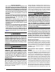
Venting Information AIR SUPPLY INLET VENT TERMINAL AREA WHERE TERMINAL IS NOT PERMITTED CANADIAN INSTALLATIONS a US INSTALLATIONS b Direct Vent (2-pipe) & Conventional Vent (1-pipe) Furnaces Direct Vent (2-pipe) Furnaces Conventional Vent (1-pipe) Furnaces 12 inches (30cm) 12 inches (30cm) 12 inches (30cm) 6 inches (15cm) for appliances < 10,000 Btuh (3kW) 6 inches (15cm) for appliances < 10,000 Btuh (3kW) 12 inches (30cm) for appliances 10,000 Btuh - 100,000 Btuh (30kW) 9 inches (23cm) for
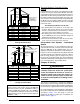
*SC & *SL Series (92.1% AFUE) HORIZONTAL VENTING w/ 2-Pipes Straps or other suitable supports at minimum 5 ft. intervals (both pipes) (Upflow Furnace Shown) Wall First support as close to furnace as possible 90° Elbows 90° Elbow COMBUSTION AIR VENT PIPE FLUE PIPE Rubber Grommet Flue Pipe must slope upward 1/4” per foot Seal / caulk around pipes at wall 7” 12” Min.
COMBUSTION AIR COMBUSTION AIR Plug Plug FLUE PIPE X Plug OPTION 1 PVC Tee FLUE PIPE See NOTE 5 See NOTE 5 Rubber Grommet OPTION 3 OPTION 2 Rubber Grommet PVC Trap See VIEW A for drain line positions VIEW -A- X Inline Drain Tube (Factory Equipped) See NOTE 4 See VIEW C for drain line positions See VIEW B for drain line positions Inline Drain Tube (Factory Supplied) See NOTE 4 Plug COMBUSTION AIR Plug Rubber Grommet FLUE PIPE 92.
Rubber Grommet See VIEW E for drain line positions X Plug See NOTE 5 FLUE PIPE See VIEW D for drain line positions FLUE PIPE 92.
Rubber Grommet See VIEW I for drain line positions X Plug See NOTE 5 FLUE PIPE See VIEW H for drain line positions FLUE PIPE 92.
COMBUSTION AIR COMBUSTION AIR Plug Plug Option 16 Plug See NOTE 5 Plug Plug PVC Tee Rubber Grommet X Option 17 Plug X Option 15 FLUE PIPE COMBUSTION AIR FLUE PIPE FLUE PIPE 92.
*SD & *SM Series (95.0 % AFUE) HORIZONTAL VENTING w/ 2-Pipes Straps or Other Suitable Supports at minimum of 5 ft. Intervals (Upflow Furnace Shown) Seal/Caulk Around Pipes at Building 90° Elbow 90° Elbow COMBUSTION AIR See Table 2 for 2” PVC pipe lengths (field supplied) Upward Pitch - 1/4” per foot (Flue Pipe) FLUE PIPE Coupling with 2 Hose Clamps (Optional) 90° Elbow First support placed as close to furnace connection as possible 12” Min.
95.
95.0% HORIZONTAL LEFT - 1 PIPE OPTION Rubber Grommet Option 26 FLUE PIPE Option 25 FLUE PIPE 95.0% HORIZONTAL RIGHT - 1 PIPE OPTION Rubber Grommet COMBUSTION AIR COMBUSTION AIR See VIEW Q for drain line positions See VIEW R for drain line positions Plug Plug Inline Drain (Factory Supplied) See NOTE 3 VIEW -Q- VIEW -RInline Drain (Factory Supplied) See NOTE 2 Collector Box Drain (Factory Equipped) See NOTE 2 Collector Box Drain (Factory Equipped) See NOTE 2 NOTES: 1.
Option 30 Plug PVC Tee X FLUE PIPE See NOTE 5 Plug Option 29 COMBUSTION AIR COMBUSTION AIR Plug X FLUE PIPE Rubber Grommet PVC Trap Option 31 Plug COMBUSTION AIR FLUE PIPE 95.
TROUBLESHOOTING If the furnace fails to operate check the following: • Is the thermostat operating properly? • Are the blower compartment door(s) in place? • Is the furnace disconnect closed? • Has the circuit breaker tripped or the control board fuse burned open? • Is the gas turned on? • Are any manual reset switches open? • Is the filter dirty or plugged? • Is the flame sensor coated? (Remove and clean with steel wool.
Flame Sensor Finish Igniter Flange Roll-Out Burner Switch Assembly Gas Manifold Control Board Main Air Limit Switch Gas Valve Vent Limit Switch Pressure Switch - Condensate (‘B’, ‘C’, & ‘D’ cabinets only) Transformer Inducer Assembly Pressure Switch (Inducer) Blower Door Switch Blower Assembly *SC Series Upflow / Horizontal Furnace Flame Sensor Finish Flange Roll-Out Switch Burner Assembly Igniter Main Air Limit Switch Inducer Limit Switch Pressure Switch (Inducer) Inducer Assembly Blower Door Sw
Blower Assembly Finish Flange Control Board Blower Door Switch (behind blower panel) Transformer Vent Limit Switch Inducer Assembly Pressure Switch Main Air Limit Switch Gas Valve Gas Manifold Igniter Burner Assembly Roll-Out Switch Flame Sensor *SL Series Downflow Furnace Finish Flange Blower Assembly (behind blower panel) Furnace Control Board Blower Door Switch (behind blower panel) Transformer Inducer Limit Switch Inducer Assembly Pressure Switch Gas Valve Igniter Flame Sensor Burner Ass
INSTALLATION / PERFORMANCE CHECK LIST ELECTRICAL SYSTEM ATTENTION INSTALLERS: It is your responsibility to know this product better than your customer. This includes being able to install the product according to strict safety guidelines and instructing the customer on how to operate and maintain the equipment for the life of the product. Safety should always be the deciding factor when installing this product and using common sense plays an important role as well.