
Installation Guide


14
Existing Installations
When an existing furnace is removed from a vent system
serving other appliances, the existing vent system may
not be sized properly to vent the remaining appliances
(For example: water heater). An improperly sized venting
system can result in the formation of condensate, leakage,
or spillage. The existing vent system should be checked
to make sure it is in compliance with NFGC and must be
brought into compliance before installing the furnace.
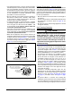
NOTE: If replacing an existing furnace, it is possible you
will encounter an existing plastic venting system that is
subject to a Consumer Product Safety Commission recall.
The pipes involved in the recall are High Temperature
Plastic Vent (HTPV). Ifyourventingsystemcontains
thesepipes DONOTreusethisventingsystem! This
recall does not apply to other plastic vent pipes, such
as white PVC or CPVC. Check for details on the CPSC
website or call their toll-free number (800) 758-3688.
CondensateDisposal
The method for disposing of condensate varies according
to local codes. Consult your local code or authority having
jurisdiction. Neutralizer kit P/N 902377 is available for
use with this furnace. Pleasefollowtheinstructions
providedwiththekit.
This furnace has multiple options for positioning the vent
pipe as described in the, Vent and Inducer Assembly
Options section (page 18). Each of the condensate
drain lines must be J-trapped using field supplied parts.
After the condensate lines are J-trapped, they may be
combined together when routed to the drain.
For Installations where there is limited clearance for the
J-Trap (such as an attic where it may be installed between
ceiling joists), either side of the J-Trap can be shortened
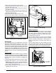
to a minimum of 3 Inches. See Figure 11 (page 16).
CIRCULATING AIR REQUIREMENTS
WARNING:
Donotallowcombustionproductstoenterthe
circulating air supply. Failure to prevent the
circulation of combustion products into the
livingspacecancreatepotentiallyhazardous
conditions including carbon monoxide
poisoningthatcouldresultinpersonalinjury
ordeath.
All return ductwork must be secured to
the furnace with sheet metal screws. For
installations in conned spaces, all return
ductwork must be adequately sealed. When
returnairisprovidedthroughthebottomofthe
furnace,thejointbetweenthefurnaceandthe
returnairplenummustbeairtight.
Thesurfacethatthefurnaceismountedonmust
providesoundphysicalsupportofthefurnace
withnogaps,cracksorsaggingbetweenthe
furnaceandtheoororplatform.
Returnair andcirculatingairductworkmust
notbeconnectedtoanyotherheatproducing
devicesuchasareplaceinsert,stove,etc.This
mayresultinre,explosion,carbonmonoxide
poisoning,personalinjury,orpropertydamage.
Plenums&AirDucts
• Plenumsandairductsmustbeinstalledinaccordance
with the Standard for the Installation of Air Conditioning
and Ventilating Systems (NFPA No. 90A) or the
Standard for the Installation of Warm Air Heating and
Air Conditioning Systems (NFPA No. 90B).
• Table 6 (page 35), Table 7 (page 36), Table 8 (page
37), and Table 9 (page 38) contain the maximum
airflow and temperature rise data for each furnace input
rate. If the maximum airflow is 1,600 CFM or more, it is
recommended that two openings be used for return air
on upflow furnaces. Downflow furnaces can only use
one return opening.
• It is recommended that the outlet duct contain a
removable access panel. The opening should be
accessible when the furnace is installed in service and
shall be of a size that smoke or reflected light may be
observed inside the casing to indicate the presence of
leaks in the heat exchanger. The cover for the opening
shall be attached in a way that prevent leaks.
• Ifoutside air is used as return air to the furnace for
ventilation or to improve indoor air quality, the system
must be designed so that the return air is not less than
60° F (15° C) during operation. If a combination of indoor
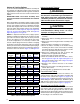
Winter Design
Temperature
MaximumFluePipeLength(FEET)
inUnconditioned&ExteriorSpaces
WithoutInsulation WithInsulation*
20 45 70
0 20 70
-20 10 60
*NOTE: Insulation thickness greater than 3/8 inch, based on an
R value of 3.5 (ft x F x hr) / (BTU x in.)
Table2.Vent Protection