
Installation Guide

31
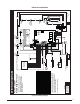
OPERATING SEQUENCE
The operating sequences for the heating, cooling, and
fan modes are described below. Refer to the field and
furnace wiring diagrams: Figure 27 (page 28), Figure
28 (page 29) and Figure 33 (page 39).
(EATING#YCLE
1. The thermostat calls for heat by energizing the W
terminal with 24VAC.
2. The control verifies the pressure switch is open.
3. If the pressure switch is open, the control energizes the
inducer and waits for the pressure switch to close. The
pressure switch must close within 10 seconds.
4. The control runs the inducer for a 30 second pre-purge.
5. The control energizes the Hot Surface Igniter (HSI)
output for the appropriate warm-up time limit.
6. The control energizes the main gas valve for 3 seconds.
7. If the flame proved and ignites the gas, the control de-
energizes the HSI. The gas valve and inducer remains
energized. The control goes to blower on delay.
8. If flame is present, the control energizes the blower on
the selected HEAT speed 30 seconds after the gas valve
opened. The gas valve and inducer remain energized.
9. When the thermostat demand for heat is satisfied, the
control de-energizes the gas valve. The Inducer output
remains on for a 30 second post-purge period.
10.Blower off timing begins when the thermostat is
satisfied. The control will operate at the selected HEAT
speed of 60, 90, 120, or 180 seconds. If the blower off
delay jumper is not present, the fan should still operate
for 120 seconds at the selected HEAT speed. The
Indoor blower motor is de-energized after a blower off
delay as selected by the movable jumper.
#OOLING#YCLE
1. The thermostat calls for cooling by energizing the Y
terminal with 24VAC.
2. The control energizes the blower in cooling speed and
sends 24VAC to the contactor in the condensing unit
3. When the thermostat removes the call for cooling, the
contactor in the outdoor condensing unit is de-energized
and the control continues to run the fan for a period of
60 seconds.
Fan Mode
s 7HEN THE THERMOSTAT ENERGIZES THE G terminal for
continuous fan (without calling for heat or cooling), the
screw all the way out from the valve, turn the screw
slowly.
d.) Replace and tighten the regulator capscrew over
the adjustment screw.
6ERIFYING!DJUSTING4EMPERATURE2ISE
After installation of the furnace, confirm the temperature
rise of the furnace is within the limits specified on the rating
plate. Any temperature rise outside the specified limits
could result in premature failure of the heat exchanger.
1. Place thermometers in the return and supply air stream
as close to the furnace as possible. The thermometer on
the supply air side must be shielded from direct radiation
from the heat exchanger to avoid false readings.
2. Adjust all registers and duct dampers to the desired
position and run the furnace for 10 to 15 minutes before
taking any temperature readings. The temperature rise
is the difference between the supply and return air
temperatures.
For typical duct systems, the temperature rise will fall
within the limits specified on the rating plate with the
blower speed at the factory recommended setting. If the
measured temperature rise is outside the specified limits,
it may be necessary to change the speed of the blower.
NOTE: Lowering the blower speed will increase the
temperature rise and a higher blower speed will decrease
the temperature rise.
The furnace is equipped with a multi-speed motor. Heating
and cooling speed selection is made by moving the switch
on the integrated control located in the furnace.
6ERIFYING"URNER/PERATION
CAUTION:
4HEDOOROVERTHEBURNERSMAYONLYBEOPEN
FORINSPECTIONPURPOSESONLY4HEDOORMUSTBE
INSTALLEDDURINGUNATTENDEDOPERATION
1. Remove the burner compartment door.
2. Set the thermostat above room temperature and observe
the ignition sequence. NOTE: The burner flame should
carry over immediately between all burners without
lifting off, curling, or floating. The flames should be blue,
without yellow tips.
3. After validating the flame, change thermostat setting to
below room temperature.
4. Verify the burner flame is completely extinguished.
5. Replace the burner compartment door.
6ERIFYING/PERATIONOFTHE3UPPLY!IR,IMIT
3WITCH
NOTE: A properly functioning limit switch should turn off
the gas valve when the return is blocked (time depends
on how well the return air is blocked). The circulating air
and combustion blowers should continue to run when the
limit switch opens.
1. Verify the blower door is securely mounted in place and
that there is power to the furnace.
2. Block the return airflow to the furnace by installing a
close-off plate in place of or upstream of the filter(s).
3. Set the thermostat above room temperature and observe
the Operating Sequence.
4. Remove the close-off immediately after the limit switch
opens. If the furnace continues to operate with no return
air, set the thermostat below room temperature, shut
off power to the furnace, and replace the limit switch.