
Installation Guide

46
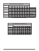
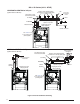
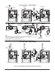
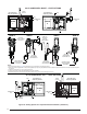
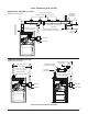
92.1% HORIZONTAL RIGHT - 1 PIPE OPTIONS
Plug
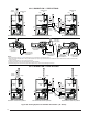
VIEW -D-
VIEW -E-
VIEW -F-
VIEW -G-
COMBUSTION
AIR
FLUE PIPE
OPTION
7
OPTION
8
COMBUSTION
AIR
Rubber
Grommet
See VIEW D for
drain line positions
See VIEW E for
drain line positions
Plug
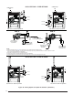
FLUE PIPE
OPTION
10
FLUE PIPE
Rubber
Grommet
OPTION
9
COMBUSTION
AIR
See VIEW F for
drain line positions
Plug
FLUE PIPE
COMBUSTION
AIR
Plug
See VIEW G for
drain line positions
Plug
Plug
Plug
Plug
Rubber
Grommet
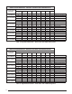
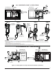
92.1% HORIZONTAL LEFT - 1 PIPE OPTIONS
Drain Line
Attached to
PVC Trap
(Field Supplied)
Collector Box Drain
(Factory Equipped)
See NOTE 2
Inline Drain
(Factory Supplied)
See NOTE 4
Inline Drain
(Field Supplied)
See NOTES 2 & 3
Inline Drain
(Field Supplied)
See NOTES 2 & 3
Collector Box Drain
(Factory Equipped)
See NOTE 2
Inline Drain
(Field Supplied)
See NOTES 2 & 3
X
See
NOTE 5
X
See
NOTE 5
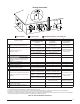
Figure 36. 6ENTING/PTIONSFOR0IPE(ORIZONTAL)NSTALLATIONS3#3ERIES
NOTES:
1. See Accessories section (
page 20) for optional PVC Tee configurations and drainage options.
2. Drain lines must be trapped with a J-Trap or field supplied loop. Traps may be positioned inside or outside the cabinet. All drain lines must be routed externally from
the cabinet.
3. Inline drain is required only if “X” is greater than 6 feet.
4. Tubing needs to be cut to length and attached during unit installation.
5. Horizontal piping from inducer to flue pipe must be sloped 1/4” per foot to ensure drainage to PVC trap.