
Installation Guide


25
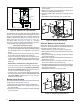
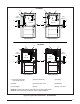
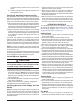
(1) Automatic Gas Valve
(w/ manual shut-off)
(2) Burner Assembly (3) Dripleg
(4) Elbow (5) Ground Joint Union (6) Manifold
(7) Pipe Nipple (8) Plug (9) Shut - Off Valve
NOTE A: Consult local codes for Shut-Off Valve location requirements
NOTE B: Inducer assembly omitted for clarity of pipe installation.
Figure 25. 4YPICAL'AS#ONNECTIONS5PmOW-ODELS
6
4
2
*SC SERIES
1
See
Note “B”
7
See
Note “B”
Right Side Entry
Left Side Entry
1
7
4
See
Note “A”
See
Note “A”
3
9
5
8
9
3
5
6
2
6
4
2
*SD SERIES
1
See
Note “B”
See
Note “B”
Right Side Entry
Left Side Entry
1
7
See
Note “A”
See
Note “A”
3
9
5
9
3
5
6
2
7
8
4