Inverter Room Air Conditioner Installation Manual KSV26CRE, KSV26HRE, KSV35CRE, KSV35HRE, KSV53HRE, KSV62HRE, KSV70CRE, KSV70HRE, KSV80HRE Refrigerant R32
Congratulations Contents Congratulations and thank you for choosing our Inverter air conditioner. We are sure you will find your new air conditioner a pleasure to use. Before you use the air conditioner, we recommend that you read through the entire user manual, which provides the description of the air conditioner and its functions. Important safety instructions............................................
Important safety instructions Please read this installation manual and the user manual before installation and carefully store in a handy place for later reference. Inside you will find many helpful hints on how to install and test the air conditioner properly. Electrical work must be installed by a licensed electrician. Be sure to use the correct rating of the power plug and main circuit for the model to be installed.
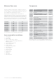
Minimum floor areas Components Your air conditioner is designed to condition the air for a certain range of room sizes, please ensure the selection of your air conditioner complies with the Kelvinator selection tool available from www.kelvinator.com.au This product uses refrigerant R32. Certain levels of refrigerant require minimum room sizes. Please ensure that these minimum room sizes are adhered to for standard installations (7.5m pipe length).
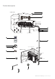
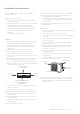
Product description Indoor unit space to the ceiling 15cm or more 2 3 1 space to the wall 15cm or more 15cm or more 8 25 0 c m 200cm or more or more space to the wall air outlet side 9 10 space to the floor 4 Fan Mode Light Turbo Healthy Timer-Off Swing 11 Temp Timer-On Clock I feel Eco 5 6 50cm or more space to obstruction Outdoor unit 7 air inlet side space to the wall 30cm or more 17 m 0c 15 cm 20 e or m or e or m or 50cm or more space to the wall 12 air outlet s
Important • If your appliance is damaged due to improper installation your warranty may be void. • Proper installation requires the use of a licensed installer. • You must keep full details of the installer including the license number and provide those details whenever you request a service for your appliance.
Installation site instructions A proper installation site is vital for correct and efficient operation of the unit. 15 Note low temperature soldering alloys are not acceptable. Avoid the following sites where: • strong heat sources, vapour, flammable gas or volatile liquids are emitted. 17 Reusable mechanical connectors may not be used within indoors or within wall or ceiling cavities where a refrigerant leak can gather.
Rooftop installation If the outdoor unit is installed on a roof structure, be sure to level the unit. Ensure the roof structure and anchoring method are adequate for the unit location. If the outdoor unit is installed on roof structures or external walls, this may result in excessive noise and vibration, and may also be classed as non-serviceable installation.
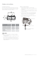
Outdoor unit installation Securing the outdoor unit Outdoor condensate drainage Anchor the outdoor unit by fixing the 4 holes existent in its base with 4 bolts and nuts of φ10 mm tightly (not included). • During heating operation, the condensate and defrosting water should be drained out reliably through the drain hose. • The drain-water hole must be plugged. Whether to plug other holes will be determined by the installer according to actual conditions.
Indoor unit installation Installing the mounting plate 1 Fit the mounting plate horizontally on the wall with five or more self-tapping screws (type ST4x25, item 3 on page 3). 2 Be sure that the mounting plate has been fixed firmly enough to withstand about 60kg. The weight should be evenly shared by every screw. 3 4 If the wall is made of brick, concrete or the like, drill five (5) or more holes of 5mm diameter in the wall. Insert clip anchor (item 2 on page 3) for appropriate mounting screws.
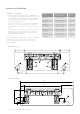
Indoor unit installation Mounting plate type C 1073 685 indoor unit 183 146 172 337 70 149 70 36 36 67 65 575 90 left 67 right Mounting plate type D 326 253 746 indoor unit 179 65 65 50 6 163 90 74 105 Kelvinator Air Conditioning Installation instructions 11
Indoor unit installation Drill piping hole Installation of drain hose 1. Determine hole positions according to the diagram. Drill one (1) hole (Ф55 or Ф70 mm) in the wall at a slight downward slant to the outdoor side. 1. Connect the drain hose to the outlet pipe of the indoor unit. Bind the joint with vinyl tape. Piping hole Model 55 KSV26CRE, KSV35CRE, KSV26HRE, KSV35HRE, KSV53HRE, 70 KSV70CRE, KSV62HRE, KSV70HRE, KSV80HRE 2.
Indoor unit installation caution 1. The insulating tube should be connected reliably with the sleeve outside the outlet pipe. 2. The drain hose should be slanted downward slightly, without distortion, bulge or fluctuation. do not block water flow with a rise 2. The drain hose can be connected at two different positions. Use the most convenient position and, if necessary, exchange the position of drain cap and drain hose.
Indoor unit installation d. Insert the drain hose into the drain hole at the rear right of the indoor unit. piping on the left rear side drain hose from the left side drain hose 3. Arrange the pipe in the most convenient direction and position.
Indoor unit installation 4. Take out the piping from body case, wrap the piping, power cords, drain hose with the tape and then make them pass through the piping hose. Do not put any object in the drain pan located in the rear of the indoor unit, as the condensed water is gathered there and piped out of the room. 5. Hang the mounting slots of the indoor unit on the upper hooks of the mounting plate and check if it is firm enough .
Indoor unit installation Refrigerant pipe connection The main cause of refrigerant leakage is due to defects in the flaring work. Carry out flaring work using the following procedure: Note: When using refrigerant R32, a reusable flared connection is the only allowed pipework on the outside of any building. Hence the supplied "once only" flare fitting must be used unless all welded connections are used. If welded connections are used, no low temperature solder is permitted.
Indoor unit installation Piping connection - indoor unit b. Wrap the insulation material around the connecting portion: a. Connecting the indoor unit tubing to the connection piping: Cover the indoor unit pipe and the connection pipe with the heat insulation material. Bind them together with vinyl tape so that there is no gap. Align the centres of the pipes and sufficiently tighten the flare nut with your hands first.
Indoor unit installation b. Then, tighten the flare nut with torque wrench until the wrench clicks. c. Positioning the indoor unit: Remove the spacer. Hook the indoor unit onto the upper portion of the mounting plate (engage the hooks of the mounting plate into the openings at the rear top of the indoor unit). Ensure that the hooks are properly seated on the mounting plate by moving the indoor unit in all directions.
Indoor unit installation Safety precautions c. In cases where the outdoor unit is installed above the indoor unit level: Wrap the piping and connecting cable from bottom to top. Form a trap to prevent water from entering the room. Secure the wrapped piping along the exterior wall using saddle or equivalent. Electrical safety rules before starting the installation: 1.
Installation Indoor electric wiring KSV26HRE, KSV35HRE models Note: for correct operation of the air conditioner and standby power modes the mains power should be supplied to the indoor unit. 1. Open the front panel and remove the wiring cover by loosening the screw. N(1) 2 4 5 wiring cover blue 2. Route the power connection cable from back of the indoor unit and pull it toward the front through the wiring hole for connection. 3.
Installation Outdoor electric wires 1. When required, remove the handle on the right side plate of outdoor unit by loosening the screw. caution After confirming the above conditions, prepare the wiring as follows: • The screws which fasten the wiring to the terminal block may N(1) 3 during transportation. come loose from2vibrations handle • Check and make sure all screws are well fixed. Otherwise, it could cause burn-out of the wires. • Be sure the circuit capacity is sufficient.
Installation Do not place drain piping as indicated below: Checking the drainage a. Open and lift the indoor unit front panel. Hold the lower part of the left and right sides of the panel, pull it against you and lift it stops with a full support from the bracket.
Installation indoor unit outdoor unit gas side liquid side hi stop valve (2-way valve) half union 5 Keep vacuuming for more than 15 minutes and make sure the reading of multimeter is -1.0 x 10 Pa (-76cmHg). Then fully close the low handle of manifold valve and stop the operation of the vacuum pump. 6 Turn the stem of the stop valve B (2-way valve) about 45 counterclockwise for 6~7 seconds after the gas coming out, then tighten the flare nut again.
Testing the air conditioner Soapy water method Operation test method Apply soapy water or liquid neutral detergent on all valves and pipe connections (A, B, C and D, refer to the figure below) involved in installation by a soft brush to check for leakage. If bubbles come out, the pipes have leakage. • Switch on power and press “ON/OFF” button on the remote controller to start the operation. Press MODE button to select the COOL, HEAT (if applicable), FAN to check if all the functions work well.
Post installation checks Items to be checked Possible malfunction Has the unit been fixed firmly? The unit may drop, shake or emit noise Have you done the refrigerant leakage test? It may cause insufficient cooling (heating) Is thermal insulation sufficient? It may cause condensation Is water drainage satisfactory? It may cause water leakage Is the voltage in accordance with the rated voltage marked on the nameplate? It may cause electric malfunction or damage the unit Is the electric wiring or
Notes 26 Notes Kelvinator Air Conditioning
Warranty FOR SALES IN AUSTRALIA AND NEW ZEALAND APPLIANCE: kELvINATOR SPLIT SYSTEM AIR CONDITIONER This document sets out the terms and conditions of the product warranties for Electrolux Appliances. It is an important document. Please keep it with your proof of purchase documents in a safe place for future reference should you require service for your Appliance. 1.
If you’d like further information about Kelvinator appliances, please visit your retailer, phone or email our Customer Care team or visit our website. telephone: 1300 363 640 fax: 1800 350 067 email: customercare@electrolux.com.au web: www.kelvinator.com.au Kelvinator. We are part of the Electrolux family. Share more of our thinking at www.electrolux.com.