
Datasheet


5© KEMET Electronics Corporation • P.O. Box 5928 • Greenville, SC 29606 (864) 963-6300 • www.kemet.com A4020_ALC10 • 1/20/2015
Snap-In Aluminum Electrolytic Capacitors – ALC10 Series, +85ºC
Shelf Life
The capacitance, ESR and impedance of a capacitor will not change signicantly after extended storage periods, however the leakage
current will very slowly increase. KEMET products are particularly stable and allow a shelf life in excess of three years at 40°C. See
sectional specication under each product series for specic data.
Re-age (Reforming) Procedure
Apply the rated voltage to the capacitor at room temperature for a period of one hour, or until the leakage current has fallen to a steady
value below the specied limit. During re-aging a maximum charging current of twice the specied leakage current or 5 mA (whichever
is greater) is suggested.
Reliability
The reliability of a component can be dened as the probability that it will perform satisfactorily under a given set of conditions for a
given length of time.
In practice, it is impossible to predict with absolute certainty how any individual component will perform; thus, we must utilize probability
theory. It is also necessary to clearly dene the level of stress involved (e.g. operating voltage, ripple current, temperature and time).
Finally, the meaning of satisfactory performance must be dened by specifying a set of conditions which determine the end of life of the
component.
Reliability as a function of time, R(t), is normally expressed as: R(t)=e-
λt
where R(t) is the probability that the component will perform satisfactorily for time t, and λ is the failure rate.
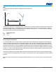
Failure Rate
The failure rate is the number of components failing per unit time. The failure rate of most electronic components follows the
characteristic pattern:
• Early failures are removed during the manufacturing process.
• The operational life is characterized by a constant failure rate.
• The wear out period is characterized by a rapidly increasing failure rate.
The failures in time (FIT) are given with a 60% condence level for the various type codes. By convention, FIT is expressed as 1 x 10
-9
failures per hour. Failure rate is also expressed as a percentage of failures per 1,000 hours.
e.g., 100 FIT = 1 x 10
-7
failures per hour = 0.01%/1,000 hours
End of Life Denition
Catastrophic Failure: short circuit, open circuit or safety vent operation
Parametric Failure:
• Change in capacitance > ±10%
• Leakage current > specied limit
• ESR > 2 x initial ESR value