
Datasheet


© KEMET Electronics Corporation • P.O. Box 5928 • Greenville, SC 29606 (864) 963-6300 • www.kemet.com C1003_C0G • 10/5/2015 18
Surface Mount Multilayer Ceramic Chip Capacitors (SMD MLCCs) – C0G Dielectric, 10 – 250 VDC (Commercial Grade)
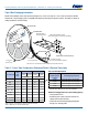
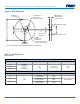
Figure 6 – Reel Dimensions
A
D (See Note)
Full Radius,
See Note
B (see Note)
Access Hole at
Slot Location
(Ø 40 mm minimum)
If present,
tape slot in core
for tape start:
2.5 mm minimum width x
10.0 mm minimum depth
W3 (Includes
flange distortion
at outer edge)
W2 (Measured at hub)
W1 (Measured at hub)
C
(Arbor hole
diameter)
Note: Drive spokes optional; if used, dimensions B and D shall apply.
N
Table 8 – Reel Dimensions
Metric will govern
Constant Dimensions — Millimeters (Inches)
Tape Size A B Minimum C D Minimum
8 mm 178 ±0.20
(7.008 ±0.008)
or
330 ±0.20
(13.000 ±0.008)
1.5
(0.059)
13.0 +0.5/-0.2
(0.521 +0.02/-0.008)
20.2
(0.795)
12 mm
16 mm
Variable Dimensions — Millimeters (Inches)
Tape Size N Minimum W
1
W
2
Maximum W
3
8 mm
50
(1.969)
8.4 +1.5/-0.0
(0.331 +0.059/-0.0)
14.4
(0.567)
Shall accommodate tape width
without interference
12 mm
12.4 +2.0/-0.0
(0.488 +0.078/-0.0)
18.4
(0.724)
16 mm
16.4 +2.0/-0.0
(0.646 +0.078/-0.0)
22.4
(0.882)