
Datasheet


2© KEMET Electronics Corporation • KEMET Tower • One East Broward Boulevard C1006_X5R_SMD • 11/9/2018
Fort Lauderdale, FL 33301 USA • 954-766-2800 • www.kemet.com
Surface Mount Multilayer Ceramic Chip Capacitors (SMD MLCCs)
X5R Dielectric, 4 – 50 VDC (Commercial Grade)
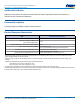
Packaging C-Spec Ordering Options Table
Packaging Type
1
Packaging/Grade
Ordering Code (C-Spec)
BulkBag/Unmarked
Notrequired(Blank)
7" Reel/Unmarked
TU
13" Reel/Unmarked
7411 (EIA 0603 and smaller case sizes)
7210(EIA0805andlargercasesizes)
7" Reel/Marked
TM
13" Reel/Marked
7040 (EIA 0603)
7215(EIA0805andlargercasesizes)
7"Reel/Unmarked/2mmpitch
2
7081
13"Reel/Unmarked/2mmpitch
2
7082
1
Default packaging is "Bulk Bag". An ordering code C-Spec is not required for "Bulk Bag" packaging.
1
The terms "Marked" and "Unmarked" pertain to laser marking option of capacitors. All packaging options labeled as "Unmarked" will contain capacitors
that have not been laser marked. Please contact KEMET if you require a laser marked option. For more information see "Capacitor Marking".
2
The 2 mm pitch option allows for double the packaging quantity of capacitors on a given reel size. This option is limited to EIA 0603 (1608 metric) case
size devices. For more information regarding 2 mm pitch option see "Tape & Reel Packaging Information".
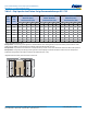
Dimensions – Millimeters (Inches)
L
B
W
S
T
EIA Size
Code
Metric Size
Code
L
Length
W
Width
T
Thickness
B
Bandwidth
S
Separation
Minimum
Mounting
Technique
0201 0603
0.60 (0.024)
±0.03 (0.001)
0.30 (0.012)
±0.03 (0.001)
See Table 2 for
Thickness
0.15 (0.006)
±0.05 (0.002)
N/A
SolderReow
Only
0402
1
1005
1.00 (0.040)
±0.05 (0.002)
0.50 (0.020)
±0.05 (0.002)
0.30 (0.012)
±0.10 (0.004)
0.30 (0.012)
0603
2
1608
1.60 (0.063)
±0.15 (0.006)
0.80 (0.032)
±0.15 (0.006)
0.35 (0.014)
±0.15 (0.006)
0.70 (0.028)
Solder Wave or
SolderReow
0805 2012
2.00 (0.079)
±0.20 (0.008)
1.25 (0.049)
±0.20 (0.008)
0.50 (0.02)
±0.25 (0.010)
0.75 (0.030)
1206
3
3216
3.20 (0.126)
±0.20 (0.008)
1.60 (0.063)
±0.20 (0.008)
0.50 (0.02)
±0.25 (0.010)
N/A
1210
4
3225
3.20 (0.126)
±0.20 (0.008)
2.50 (0.098)
±0.20 (0.008)
0.50 (0.02)
±0.25 (0.010)
SolderReow
Only
1
For capacitance values ≥ 4.7 µF add 0.15 (0.006) to the width and length tolerance dimensions.
2
For capacitance values ≥ 10 µF add 0.05 (0.002) to the length and width tolerance dimension.
3
For capacitance values ≥ 22 µF add 0.10 (0.004) to the positive bandwidth tolerance dimension.
4
For capacitance values ≥ 22 µF add 0.10 (0.004) to the length and width tolerance dimension and add 0.15 (0.006) to the positive bandwidth tolerance
dimension.