
Datasheet


© KEMET Electronics Corporation • P.O. Box 5928 • Greenville, SC 29606 (864) 963-6300 • www.kemet.com C1002_X7R_SMD • 9/21/2015 21
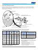
Surface Mount Multilayer Ceramic Chip Capacitors (SMD MLCCs) – X7R Dielectric, 6.3 – 250 VDC (Commercial Grade)
Packaging Information Performance Notes
1. Cover Tape Break Force: 1.0 Kg minimum.
2. Cover Tape Peel Strength: Thetotalpeelstrengthofthecovertapefromthecarriertapeshallbe:
Tape Width Peel Strength
8 mm 0.1 to 1.0 Newton (10 to 100 gf)
12 and 16 mm 0.1 to 1.3 Newton (10 to 130 gf)
Thedirectionofthepullshallbeoppositethedirectionofthecarriertapetravel.Thepullangleofthecarriertapeshallbe165°to180°
fromtheplaneofthecarriertape.Duringpeeling,thecarrierand/orcovertapeshallbepulledatavelocityof300±10mm/minute.
3. Labeling:Barcodelabeling(standardorcustom)shallbeonthesideofthereeloppositethesprocketholes.Refer to EIA
Standards 556 and 624.
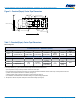
Figure 3 – Maximum Component Rotation
Ao
Bo
°
T
°
s
Maximum Component Rotation
Top View
Maximum Component Rotation
Side View
Tape Maximum
Width (mm) Rotation (
°
T
)
8,12 20
16 – 200 10
Tape Maximum
Width (mm) Rotation (
°
S
)
8,12 20
16 – 56 10
72 – 200 5
Typical Pocket Centerline
Typical Component Centerline
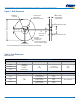
Figure 4 – Maximum Lateral Movement
0.5 mm maximum
0.5 mm maximum
8 mm & 12 mm Tape
1.0 mm maximum
1.0 mm maximum
16 mm Tape
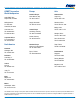
Figure 5 – Bending Radius
R
R
Bending
Radius
Embossed
Carrier
Punched
Carrier