
Datasheet


© KEMET Electronics Corporation • P.O. Box 5928 • Greenville, SC 29606 (864) 963-6300 • www.kemet.com C1002_X7R_SMD • 9/21/2015 2
Surface Mount Multilayer Ceramic Chip Capacitors (SMD MLCCs) – X7R Dielectric, 6.3 – 250 VDC (Commercial Grade)
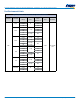
Packaging C-Spec Ordering Options Table
Packaging Type
1
Packaging/Grade
Ordering Code (C-Spec)
Bulk Bag / Unmarked
Notrequired(Blank)
7" Reel / Unmarked
TU
7" Reel / Marked
TM
7"Reel/Unmarked/2mmpitch
2
7081
13"Reel/Unmarked/2mmpitch
2
7082
1
Default packaging is "Bulk Bag". An ordering code C-Spec is not required for "Bulk Bag" packaging.
1
The terms "Marked" and "Unmarked" pertain to laser marking option of capacitors. All packaging options labeled as "Unmarked" will contain capacitors that have
not been laser marked. Please contact KEMET if you require a laser marked option. For more information see "Capacitor Marking".
2
The 2 mm pitch option allows for double the packaging quantity of capacitors on a given reel size. This option is limited to EIA 0603 (1608 metric) case size
devices. For more information regarding 2 mm pitch option see "Tape & Reel Packaging Information".
Dimensions – Millimeters (Inches)
L
B
W
S
T
EIA Size
Code
Metric
Size
Code
L
Length
W
Width
T
Thickness
B
Bandwidth
S
Separation
Minimum
Mounting
Technique
0402 1005 1.00 (0.040) ±0.05 (0.002) 0.50 (0.020) ±0.05 (0.002)
See Table 2
forThickness
0.30 (0.012) ±0.10 (0.004) 0.30 (0.012)
SolderReow
Only
0603 1608 1.60 (0.063) ±0.15 (0.006) 0.80 (0.032) ±0.15 (0.006) 0.35 (0.014) ±0.15 (0.006) 0.70 (0.028)
Solder Wave or
SolderReow
0805 2012 2.00 (0.079) ±0.20 (0.008) 1.25 (0.049) ±0.20 (0.008) 0.50 (0.02) ±0.25 (0.010) 0.75 (0.030)
1206 3216 3.20 (0.126) ±0.20 (0.008) 1.60 (0.063) ±0.20 (0.008) 0.50 (0.02) ±0.25 (0.010)
N/A
1210
1
3225 3.20 (0.126) ±0.20 (0.008) 2.50 (0.098) ±0.20 (0.008) 0.50 (0.02) ±0.25 (0.010)
SolderReow
Only
1808 4520 4.70 (0.185) ±0.50 (0.020) 2.00 (0.079) ±0.20 (0.008) 0.60 (0.024) ±0.35 (0.014)
1812 4532 4.50 (0.177) ±0.30 (0.012) 3.20 (0.126) ±0.30 (0.012) 0.60 (0.024) ±0.35 (0.014)
1825 4564 4.50 (0.177) ±0.30 (0.012) 6.40 (0.252) ±0.40 (0.016) 0.60 (0.024) ±0.35 (0.014)
2220 5650 5.70 (0.224) ±0.40 (0.016) 5.00 (0.197) ±0.40 (0.016) 0.60 (0.024) ±0.35 (0.014)
2225 5664 5.60 (0.220) ±0.40 (0.016) 6.40 (0.248) ±0.40 (0.016) 0.60 (0.024) ±0.35 (0.014)
1
For capacitance values ≥ 4.7 µF add 0.02 (0.001) to the width tolerance dimension and 0.10 (0.004) to the length tolerance dimension.