
Datasheet


© KEMET Electronics Corporation • P.O. Box 5928 • Greenville, SC 29606 • 864-963-6300 • www.kemet.com C1073_HT_C0G_RADIAL_MOLDED • 8/10/2016 12
Radial Through-Hole Multilayer Ceramic Capacitors
High Temperature 200°C, Radial, Molded, C0G Dielectric, 50 – 200 VDC (Industrial Grade)
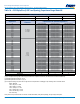
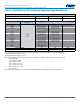
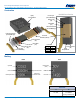
Table 3 – Ceramic Radial Tape and Reel Dimensions
Metric will govern
Constant Dimensions — Millimeters (Inches)
D
0
±0.2 (0.008)
P
0
±0.3 (0.012)
P
±0.3 (0.012)
P
2
±0.7 (0.028)
∆H
Maximum
L
1
Maximum
t
Maximum
T
Maximum
W
+ 1.0/−0.5
(+0.039/−0.020)
W
0
Minimum
W
2
Maximum
4.00 (0.157) 12.7 (0.500) 12.7 (0.500) 6. 35 (0. 25 0) 1.0 (0.039) 1.0 (0.039) 0.9 (0.035) 2.0 (0.079) 18.0 (0.709) 5.0 (0.197) 3.0 (0.118)
Variable Dimensions — Millimeters (Inches)
F
+0.6 (0.024)
−0.2 (0.008)
Note 1
P
1
±0.7 (0.028)
Note 1
H
Minimum
Note 2
H
0
±0.5 (0.630)
Note 3
2.54 (0.100) 5.08 (0.200)
18.0 (0.709) 16.0 (0.024)
4.32 (0.170) 3.89 (0.153)
5.08 (0.200) 3.81 (0.150)
5.59 (0.220) 3.25 (0.128)
6.98 (0.275) 2.54 (0.100)
7.62 (0.300) 2.24 (0.088)
9.52 (0.375) 7.62 (0.300)
10.16 (0.400) 7.34 (0.290)
12.06 (0.475) 6.35 (0.250)
14.60 (0.575) 5.08 (0.200)
17.14 (0.675) 3.81 (0.15)
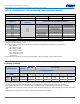
1. Measured at the egress from the carrier tape, on the component side.
2. Straight Lead con guration part types only.
3. Formed (bent) lead con guration part types only.
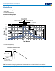
Symbol Reference Table
D
0
Sprocket Hole Diameter
P
0
Sprocket Hole Pitch
P Component Pitch
F
Lead Spacing
P
1
Sprocket Hole Center to Adjacent Component
Lead
P
2
Sprocket Hole Center to Component Center
H
Height to Seating Plane (Straight Leads Only)
H
0
Height to Seating Plane (Formed Leads Only)
H
1
Component Height Above Tape Center
∆H
Component Alignment
L
1
Lead Protrusion
t
Composite Tape Thickness
W
Carrier Tape Width
W
0
Hold-Down Tape Width
W
2
Hold-Down Tape Location