
Datasheet


© KEMET Electronics Corporation • P.O. Box 5928 • Greenville, SC 29606 • 864-963-6300 • www.kemet.com C1073_HT_C0G_RADIAL_MOLDED • 8/10/2016 8
Radial Through-Hole Multilayer Ceramic Capacitors
High Temperature 200°C, Radial, Molded, C0G Dielectric, 50 – 200 VDC (Industrial Grade)
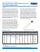
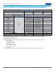
Table 2 – Performance & Reliability: Test Methods and Conditions
Stress Reference Test or Inspection Method
Solderability J–STD–002 Method A at 235°C, category 3
Temperature Cycling JESD22 Method JA–104
50 cycles (−55°C to 220°C), measurement at 24 ±4 hours after test conclusion. 30 minutes
maximum dwell time at each temperature extreme. 8 minutes maximum transition time.
Biased Humidity
MIL–STD–202 Method
103
Load humidity: 1,000 hours 85°C/85% RH and rated voltage. Add 100 K ohm resistor.
Measurement at 24 hours ±4 hours after test conclusion.
Low volt humidity: 1,000 hours 85°C/85% RH and 1.5 V. Add 100 K ohm resistor.
Measurement at 24 hours ±4 hours after test conclusion.
Immersion
MIL–STD–202 Method
104
Test condition B
Storage Life
MIL–STD–202 Method
108
Unpowered 1,000 hours at 200°C. Measurement at 24 hours ±4 hours after test conclusion.
IR Measurement at 150°C
High Temperature Life
MIL–STD–202 Method
108
1,000 hours at 200°C with rated voltage applied.
High Temperature
Lead Pull
KEMET Dened Test Peel to Failure (25ºC and 200ºC): 4 lbs (1.84 kg) minimum
Vibration
MIL–STD–202 Method
204
5g for 20 minutes, 12 cycles each of 3 orientations. Note: Use 8" X 5" PCB. 031" thick 7
secure points on one long side and 2 secure points at corners of opposite sides. Parts
mounted within 2" from any secure point. Test from 10 – 2000 Hz.
Resistance to Soldering
Heat
MIL–STD–202 Method
210
Test Condition B, Solder dip. Note: no preheat of samples.
Terminal Strength
MIL–STD–202 Method
211
Test Condition A. 454g 5 – 10 s; Bend test © 227g, 3 bends
Mechanical Shock
MIL–STD–202 Method
213
Test Condition D. Figure 1 of Method 213.
Resistance to Solvents
MIL–STD–202 Method
215
Add aqueous wash chemical – OKEM Clean or equivalent.
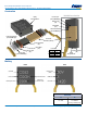
Storage & Handling
The un-mounted storage life of a through-hole (leaded) ceramic capacitor is dependent upon storage and atmospheric
conditions as well as packaging materials. While the ceramic chips enveloped under the epoxy coating themselves are quite
robust in most environments, solderability of the wire lead on the nal epoxy-coated product will be degraded by exposure
to high temperatures, high humidity, corrosive atmospheres, and long term storage. In addition, packaging materials will be
degraded by high temperature and exposure to direct sunlight–reels may soften or warp, and tape peel force may increase.
KEMET recommends storing the un-mounted capacitors in their original packaging, in a location away from direct sunlight,
and where the temperature and relative humidity do not exceed 40 degrees centigrade and 70% respectively. For optimum
solderability, capacitor stock should be used promptly, preferably within 18 months of receipt. For applications requiring
pre-tinning of components, storage life may be extended if solderability is veried. Before cleaning, bonding or molding these
devices, it is important to verify that your process does not affect product quality and performance. KEMET recommends
testing and evaluating the performance of a cleaned, bonded or molded product prior to implementing and/or qualifying any
of these processes.