
Datasheet


© KEMET Electronics Corporation • P.O. Box 5928 • Greenville, SC 29606 • 864-963-6300 • www.kemet.com C1073_HT_C0G_RADIAL_MOLDED • 8/10/2016 3
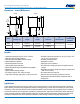
Radial Through-Hole Multilayer Ceramic Capacitors
High Temperature 200°C, Radial, Molded, C0G Dielectric, 50 – 200 VDC (Industrial Grade)
Qualication
These devices are subject to internal qualication. Details regarding test methods and conditions are referenced in Table 2,
Performance & Reliability.
Environmental Compliance
RoHS compliant and halogen-free. These devices utilize exemption 7(a) of the RoHS directive.
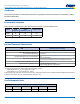
Series
RoHS
Compliant
RoHS
Exemption Code
1
Halogen Free
C052H Yes 7(a) Yes
C062H Yes 7(a) Yes
1
7(a): Lead in high melting temperature type solders
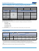
Electrical Parameters/Characteristics
Item Parameters/Characteristics
Operating Temperature Range −55°C to +200°C
Capacitance Change with Reference to
+25°C and 0 VDC Applied (TCC)
±30 ppm/ºC
Aging Rate (Maximum % Cap Loss/Decade Hour) 0%
Dielectric Withstanding Voltage
250% of rated voltage
(5±1 seconds and charge/discharge not exceeding 50 mA at 25°C)
Dissipation Factor (DF) Maximum Limit at 25ºC 0.1%
Insulation Resistance (IR) Limit at 25°C
1,000 MΩ microfarads or 100 GΩ
(Rated voltage applied for 120±5 seconds)
To obtain IR limit, divide MΩ-µF value by the capacitance and compare to GΩ limit. Select the lower of the two limits.
Capacitance and dissipation factor (DF) measured under the following conditions:
1 MHz ±100 kHz and 1.0 V
rms
±0.2 V if capacitance ≤ 1,000 pF
1 kHz ±50Hz and 1.0 V
rms
±0.2 V if capacitance > 1,000 pF
Note: When measuring capacitance it is important to ensure the set voltage level is held constant. The HP4284 and Agilent E4980 have a feature known
as Automatic Level Control (ALC). The ALC feature should be switched to "ON."
Post Environmental Limits
High Temperature Life, Biased Humidity, Moisture Resistance
Dielectric Rated DC Voltage Capacitance Value DF (%) Capacitance Shift IR
C0G All All 0.5 0.3% or ±0.25 pF 10% of Initial Limit