
Datasheet

© KEMET Electronics Corporation • P.O. Box 5928 • Greenville, SC 29606 (864) 963-6300 • www.kemet.com C1003_C0G • 3/30/2016 4
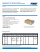
Surface Mount Multilayer Ceramic Chip Capacitors (SMD MLCCs) – C0G Dielectric, 10 – 250 VDC (Commercial Grade)
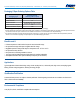
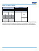
Electrical Parameters/Characteristics
Item Parameters/Characteristics
OperatingTemperatureRange −55°Cto+125°C
CapacitanceChangewithReferenceto+25°Cand0VDCApplied(TCC) ±30ppm/ºC
AgingRate(Maximum%CapacitanceLoss/DecadeHour) 0%
1
DielectricWithstandingVoltage(DWV)
250%ofratedvoltage
(5±1secondsandcharge/dischargenotexceeding50mA)
2
DissipationFactor(DF)MaximumLimit@25ºC
0.1%
3
InsulationResistance(IR)Limit@25°C
1,000megohmmicrofaradsor100GΩ
(Ratedvoltageappliedfor120±5seconds@25°C)
1
DWV is the voltage a capacitor can withstand (survive) for a short period of time. It exceeds the nominal and continuous working voltage of the capacitor.
2
Capacitance and dissipation factor (DF) measured under the following conditions:
1 MHz ±100 kHz and 1.0 Vrms ±0.2 V if capacitance ≤ 1,000 pF
1 kHz ±50 Hz and 1.0 Vrms ±0.2 V if capacitance > 1,000 pF
3
To obtain IR limit, divide MΩ-µF value by the capacitance and compare to GΩ limit. Select the lower of the two limits.
Capacitance and Dissipation Factor (DF) measured under the following conditions:
Note: When measuring capacitance it is important to ensure the set voltage level is held constant. The HP4284 and Agilent E4980 have a feature known as
Automatic Level Control (ALC). The ALC feature should be switched to "ON."
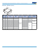
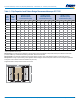
Post Environmental Limits
High Temperature Life, Biased Humidity, Moisture Resistance
Dielectric
Rated DC
Voltage
Capacitance
Value
Dissipation Factor
(Maximum%)
Capacitance
Shift
Insulation
Resistance
C0G All All 0.5
0.3%or±0.25pF
10%ofInitialLimit