
Brochure


© KEMET Electronics Corporation • P.O. Box 5928 • Greenville, SC 29606 (864) 963-6300 • www.kemet.com F3054_C44H_RADIAL • 7/2/2014 5
Power and AC Film Capacitors
Aluminum Can Power Film Capacitors – C44H Series, 330 – 440 VAC, 700 – 1,000 VDC, for PFC and AC Filter
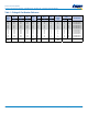
Lifetime Expectancy/Failure Quota Graphs
Power Losses and Hot Spot Temperature Calculation
At each frequency, the Power Losses are the sum of:
1. Dielectric Power Losses
P
D
(f
i
) = 2 * π * f
i
* C * V(f
i
)
2
* tgδ
0
which can be alternatively calculated as
P
D
(f
i
) =
I(f
i
)
2
* tgδ
0
2 * π * f
i
* C
where: tgδ
0
= 2 * 10
-4
2. Joule Power Losses:
P
J
(f
i
) = Rs * I(f
i
)
2
The Total Power Losses are the sum of the components at each frequency:
( ) ( )
[ ]
∑
+=
i
iJiDT
fPfPP
The Thermal Jump in the Hot Spot is:
ΔT
HS
= P
T
* R
th-hs
The Hot Spot Temperature is:
T
HS
= T
a
+ ΔT
HS
Limits for the formulas
The limits listed below should not be exceeded:
1.
2.
T
HS
= T
a
+ ΔT
HS
≤ (T
HS
)
MAX
Where T
a
is the ambient temperature (steady state temperature of the cooling air
owing around the capacitor, measured at 100 mm of distance from the capacitor
and at a height of 2/3 height of the capacitor).
3. Maximum case temperature (T
CASE
) ≤ 70°C
Example of calculation
Part Number: C44HKGR6100AASJ
Rated V
RMS
= 440 [V
RMS
]
Rated I
RMS
= 30 [A]
R
s
= 4.1 [mΩ]
R
th
= 5.0 [°C/W]
Fundamental Frequency F
1
= 50 [Hz]
Ripple Frequency F
2
= 7000 [Hz]
Fundamental Voltage V
1
= 440 [V~]
Ripple Current I
2
= 27 [A]
T
a
= 35°C
I
1
= I(50) = 2 * π * 50 * 100 * 10
-6
* 440 = 13.8 [A]
V
2
= V(7000) = [27/(2 * π * 7000 * 100 * 10
-6
)] = 6.14 [V]
I
RMS
= √(13.8
2
+ 27
2
) = 30 ≤ 30 → Admitted
V
RMS
= √(440
2
+ 6.1
2
) = 440 ≤ 440 → Admitted
P
D
(50) = 2 * π * 50 * 100 * 10
-6
* 440
2
* 2 * 10
-4
= 1.22 [W]
P
D
(7000) = [27
2
/(2 * π * 7000 * 100 * 10
-6
)] * 2 * 10
-4
= 0.03 [W]
P
J
(50) = 3.5 * 10
-3
* [(2 *π * 50 * 100 * 10
-6
* 440)
2
] = 0.67 [W]
P
J
(7000) = 3.5 * 10
-3
* 27
2
= 2.55 [W]
P
T
= 1.22 + 0.03 + 0.78 + 3 = 5 [W]
ΔT
HS
= 5 * 5 = 25 [°C]
T
HS
= Ta + ΔT
HS
T
HS
= 35 + 25 = 60 [°C] →OK since hot spot temperature is less
than maximum admitted
Expected Life @ T
HS
= 70°C → 100,000 hours (see lifetime curve)
Expected Life @ T
HS
= 60°C → 140,000 hours (see lifetime curve)
0,60
0,70
0,80
0,90
1,00
1,10
1,20
1,30
1,40
100 1.000 10.000 100.000 1.000.000
≤60°C
70°C
75°C
Lifetime curve C44H series
Hot Spot
temperature
[°C]
Lifetime Expectancy [h]
Voltage Ratio [U/U
RMS
]
V = Operating Voltage [VAC]
V
rms
= Rated Voltage [VAC]
RMS
i
i
VfV ≤
∑
2
)(
RMS
i
i
IfI ≤
∑
2
)(
1
10
100
1000
0,6 0,7 0 ,8 0,9 1 1,1
FIT
Voltage Ratio [U/Urms]
FIT @ Hot Spot Temperatures
75
70
≤60