
Datasheet


9© KEMET Electronics Corporation • KEMET Tower • One East Broward Boulevard C1017_X7R_ARRAY_SMD • 12/5/2018
Fort Lauderdale, FL 33301 USA • 954-766-2800 • www.kemet.com
9
Surface Mount Multilayer Ceramic Chip Capacitors (SMD MLCCs)
Capacitor Array, X7R Dielectric, 10 – 200 VDC (Commercial & Automotive Grade)
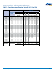
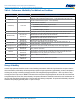
Table 4 – Performance & Reliability: Test Methods and Conditions
Stress Reference Test or Inspection Method
Terminal Strength JIS–C–6429 Appendix 1, Note: Force of 1.8 kg for 60 seconds.
Board Flex JIS–C–6429
Appendix 2, Note: Standard termination system – 2.0 mm (minimum) for all except 3 mm
for C0G. Flexible termination system – 3.0 mm (minimum).
Solderability J–STD–002
Magnication 50 X. Conditions:
a) Method B, 4 hours at 155°C, dry heat at 235°C
b) Method B at 215°C category 3
c) Method D, category 3 at 260°C
Temperature Cycling JESD22 Method JA–104 1,000 Cycles (−55°C to +125°C). Measurement at 24 hours ±4 hours after test conclusion.
Biased Humidity
MIL–STD–202
Method 103
Load Humidity: 1,000 hours 85°C/85% RH and rated voltage. Add 100 K ohm resistor.
Measurement at 24 hours ±4 hours after test conclusion.
Low Volt Humidity: 1,000 hours 85°C/85% RH and 1.5 V. Add 100 K ohm resistor.
Measurement at 24 hours ±4 hours after test conclusion.
Moisture Resistance
MIL–STD–202
Method 106
t = 24 hours/cycle. Steps 7a and 7b not required.
Measurement at 24 hours ±4 hours after test conclusion.
Thermal Shock
MIL–STD–202
Method 107
−55°C/+125°C. Note: Number of cycles required – 300, maximum transfer time – 20
seconds, dwell time – 15 minutes. Air – air.
High Temperature Life
MIL–STD–202
Method 108/EIA–198
1,000 hours at 125°C (85°C for X5R, Z5U and Y5V) with 2 X rated voltage applied.
Storage Life
MIL–STD–202
Method 108
150°C, 0 VDC for 1,000 hours.
Vibration
MIL–STD–202
Method 204
5 g's for 20 min., 12 cycles each of 3 orientations. Note: Use 8" X 5" PCB 0.031" thick 7
secure points on one long side and 2 secure points at corners of opposite sides. Parts
mounted within 2" from any secure point. Test from 10 – 2,000 Hz
Mechanical Shock
MIL–STD–202
Method 213
Figure 1 of Method 213, Condition F.
Resistance to Solvents
MIL–STD–202
Method 215
Add aqueous wash chemical, OKEM clean or equivalent.
Storage & Handling
Ceramic chip capacitors should be stored in normal working environments. While the chips themselves are quite robust in
other environments, solderability will be degraded by exposure to high temperatures, high humidity, corrosive atmospheres,
and long term storage. In addition, packaging materials will be degraded by high temperature – reels may soften or warp
and tape peel force may increase. KEMET recommends that maximum storage temperature not exceed 40ºC and maximum
storage humidity not exceed 70% relative humidity. Temperature uctuations should be minimized to avoid condensation on
the parts and atmospheres should be free of chlorine and sulfur bearing compounds. For optimized solderability chip stock
should be used promptly, preferably within 1.5 years of receipt.