
Datasheet


17© KEMET Electronics Corporation • KEMET Tower • One East Broward Boulevard C1017_X7R_ARRAY_SMD • 12/5/2018
Fort Lauderdale, FL 33301 USA • 954-766-2800 • www.kemet.com
17
Surface Mount Multilayer Ceramic Chip Capacitors (SMD MLCCs)
Capacitor Array, X7R Dielectric, 10 – 200 VDC (Commercial & Automotive Grade)
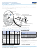
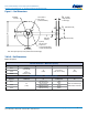
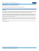
Figure 6 – Reel Dimensions
A
D (See Note)
Full Radius,
See Note
B (see Note)
Access Hole at
Slot Location
(Ø 40 mm minimum)
If present,
tape slot in core
for tape start:
2.5 mm minimum width x
10.0 mm minimum depth
W
3
(Includes
flange distortion
at outer edge)
W
2
(Measured at hub)
W
1
(Measured at hub)
C
(Arbor hole
diameter)
Note: Drive spokes optional; if used, dimensions B and D shall apply.
N
Table 8 – Reel Dimensions
Metric will govern
Constant Dimensions — Millimeters (Inches)
Tape Size A B Minimum C D Minimum
8 mm 178 ±0.20
(7.008 ±0.008)
or
330 ±0.20
(13.000 ±0.008)
1.5
(0.059)
13.0 +0.5/−0.2
(0.521 +0.02/−0.008)
20.2
(0.795)
12 mm
16 mm
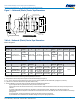
Variable Dimensions — Millimeters (Inches)
Tape Size N Minimum W
1
W
2
Maximum W
3
8 mm
50
(1.969)
8.4 +1.5/−0.0
(0.331 +0.059/−0.0)
14.4
(0.567)
Shall accommodate tape
width without interference
12 mm
12.4 +2.0/−0.0
(0.488 +0.078/−0.0)
18.4
(0.724)
16 mm
16.4 +2.0/−0.0
(0.646 +0.078/−0.0)
22.4
(0.882)