
Datasheet


12© KEMET Electronics Corporation • P.O. Box 5928 • Greenville, SC 29606 • 864-963-6300 • www.kemet.com S6011_FC • 3/29/2017
Supercapacitors – FC Series
Measurement Conditions cont’d
Capacitance (Discharge System)
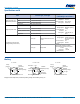
As shown in the diagram below, charging is performed for a duration of 30 minutes once the voltage of the capacitor
terminal reaches 5.5 V. Then, use a constant current load device and measure the time for the terminal voltage to drop
from 3.0 to 2.5 V upon discharge at 0.22 mA per 0.22 F, for example, and calculate the static capacitance according to the
equation shown below.
Note: The current value is 1 mA discharged per 1 F.
Capacitance (Discharge System – 3.5 V)
As shown in the diagram below, charging is performed for a duration of 30 minutes once the voltage of the capacitor
terminal reaches 3.5 V. Then, use a constant current load device and measure the time for the terminal voltage to drop from
1.8 to 1.5 V upon discharge at 1.0 mA per 1.0 F, for example, and calculate the static capacitance according to the equation
shown below.
Capacitance (Discharge System – HV Series)
As shown in the diagram below, charging is performed for a duration of 30 minutes once the voltage of the capacitor
terminal reaches maximum operating voltage. Then, use a constant current load device and measure the time for the
terminal voltage to drop from 2.0 to 1.5 V upon discharge at 1.0 mA per 1.0 F, and calculate the static capacitance according
to the equation shown below.
36 Super Capacitors Vol.13
9. Measurement Conditions
V
C
R
C
E
O
Swich
C
+
–
E
O
: 3.0 (V) … Product with maximum operating voltage
3.5 V
5.0 (V) … Product with maximum operating voltage
5.5 V
6.0 (V) … Product with maximum operating voltage
6.5 V
10.0 (V) … Product with maximum operating voltage
11 V
12.0 (V) … Product with maximum operating voltage
12 V
τ: Time from start of charging until Vc becomes
0.632E
0
(V) (sec)
R
C
: See table below (Ω).
Capacitance: C = (F) (9)
τ
R
C
Capacitance (Discharge System)
In the diagram below, charging is performed for a duration of 30 minutes, once the voltage of the condensor terminal
reaches 5.5 V.
Then, use a constant current load device and measure the time for the terminal voltage to drop from 3.0 to 2.5 V upon
discharge at 0.22 mA for 0.22 F, for example, and calculate the static capacitance according to the equation shown below.
Note: The current value is 1 mA discharged per 1F.
A
V
C R
5.5V
SW
0.22mA(I)
30 min. T1 T2
V1 : 2.5V
V1 : 3.0V
5.5V
V
1
V2
Voltage
Duration (sec.)
Table 3 Capacitance measurement
Capactance:C= (F)
I×(T
2
-T
1
)
V
1
-V
2
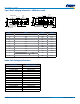
(1) Capacitance ( Charge System )
Capacitance is calculated from expression (9) by measuring the charge time constant (τ) of the capacitor (C). Prior to
measurement, short between both pins of the capacitor for 30 minutes or more to let it discharge. In addition, follow the indication
of the product when determining the polarity of the capacitor during charging.
FA FE FS
FY
FR
FM, FME
FMR, FML
FMC
FG
FGR
FGH FT
FC,
FCS
FYD FYH FYL
0.010F – – – – – 5000 Ω – 5000 Ω – 5000 Ω – – –
0.022F 1000 Ω – 1000 Ω 2000 Ω 2000 Ω 2000 Ω 2000 Ω 2000 Ω – 2000 Ω – –
Discharge
0.033F – – – – – – – Discharge – – – – –
0.047F 1000 Ω 1000 Ω 1000 Ω 2000 Ω 1000 Ω 2000 Ω 1000 Ω 2000 Ω 1000 Ω 2000 Ω – – –
0.10F 510 Ω 510 Ω 510 Ω 1000 Ω 510 Ω – 1000 Ω 1000 Ω 1000 Ω 1000 Ω
Discharge
510 Ω
Discharge
0.22F 200 Ω 200 Ω 200 Ω 510 Ω 510 Ω – 510 Ω
0H: Discharge
0V: 1000 Ω
– 1000 Ω
Discharge
200 Ω
Discharge
0.33F – – – – – – – –
Discharge
– – – –
0.47F 100 Ω 100 Ω 100 Ω 200 Ω 200 Ω – 200 Ω – – 1000 Ω
Discharge
100 Ω
Discharge
1.0F 51 Ω 51 Ω 100 Ω 100 Ω 100 Ω – 100 Ω – – 510 Ω
Discharge
100 Ω
Discharge
1.4F – – – 200 Ω – – – – – – – – –
1.5F – 51 Ω – – – – – – – 510 Ω – – –
2.2F – – – 100 Ω – – – – – 200 Ω – 51 Ω –
3.3F – – – – – – – – – – – 51 Ω –
4.7F – – – – – – – – – 100 Ω – – –
5.0F – – 100 Ω – – – – – – – – – –
5.6F – – – – – – – – – – – 20 Ω –
*Capacitance values according to the constant current discharge method.
*HV series capacitance is measured by discharge system.
Super Capacitors Vol.13 37
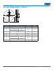
Capacitance (Discharge System:3.5V)
In the diagram below, charging is performed for a duration of 30 minutes, once the voltage of the capacitor terminal reaches 3.5V.
Then, use a constant current load device and measure the time for the terminal voltage to drop from 1.8 to 1.5V upon
discharge at 1 mA per 1F, and calculate the static capacitance according to the equation shown below.
Capacitance (Discharge System:HVseries)
In the diagram below, charging is performed for a duration of 30 minutes, once the voltage of the capacitor terminal reaches
Max. operating voltage.
Then, use a constant current load device and measure the time for the terminal voltage to drop from 2.0 to 1.5V upon discharge
at 1 mA per 1F, and calculate the static capacitance according to the equation shown below.
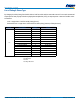
Equivalent series resistance (ESR)
ESR shall be calculated from the equation below.
Current (at 30 minutes after charging)
Current shall be calculated from the equation below.
Prior to measurement, both lead terminals must be short-circuited for a minimum of 30 minutes.
The lead terminal connected to the metal can case is connected to the negative side of the power supply.
Eo: 2.5Vdc (HVseries 50F)
2.7Vdc (HVseries except 50F)
3.0Vdc (3.5V type)
5.0Vdc (5.5V type)
Rc: 1000Ω (0.010F, 0.022F, 0.047F)
100Ω (0.10F, 0.22F, 0.47F)
10Ω (1.0F, 1.5F, 2.2F, 4.7F)
2.2Ω (HVseries)
Self-discharge characteristic (0H: 5.5V products)
The self-discharge characteristic is measured by charging a voltage of 5.0 Vdc (charge protection resistance: 0Ω) according
to the capacitor polarity for 24 hours, then releasing between the pins for 24 hours and measuring the pin-to-pin voltage.
The test should be carried out in an environment with an ambient temperature of 25℃ or below and relative humidity of 70%
RH or below.
A
V
C R
3.5V
SW
30 minutes
T
1 T2
V2 : 1.5V
V1 : 1.8V
3.5V
(V)
V
1
V2
Time (sec.)
A
V
C R
3.5V
SW
V2 : 1.5V
V1 : 2.0V
3.5V
(V)
V
1
V2
Time (sec.)
30 minutes
T
1 T2
C= (F)
I×(T
2
-T
1
)
V
1
-V
2
C= (F)
I×(T
2
-T
1
)
V
1
-V
2
Current= (A)
V
R
R
C
ESR= (Ω)
V
C
0.01
C
10mA
V
C
f:1kHz
C
SW
R
C
E
O
+
-
V
R
Super Capacitors Vol.13 37
Capacitance (Discharge System:3.5V)
In the diagram below, charging is performed for a duration of 30 minutes, once the voltage of the capacitor terminal reaches 3.5V.
Then, use a constant current load device and measure the time for the terminal voltage to drop from 1.8 to 1.5V upon
discharge at 1 mA per 1F, and calculate the static capacitance according to the equation shown below.
Capacitance (Discharge System:HVseries)
In the diagram below, charging is performed for a duration of 30 minutes, once the voltage of the capacitor terminal reaches
Max. operating voltage.
Then, use a constant current load device and measure the time for the terminal voltage to drop from 2.0 to 1.5V upon discharge
at 1 mA per 1F, and calculate the static capacitance according to the equation shown below.
Equivalent series resistance (ESR)
ESR shall be calculated from the equation below.
Current (at 30 minutes after charging)
Current shall be calculated from the equation below.
Prior to measurement, both lead terminals must be short-circuited for a minimum of 30 minutes.
The lead terminal connected to the metal can case is connected to the negative side of the power supply.
Eo: 2.5Vdc (HVseries 50F)
2.7Vdc (HVseries except 50F)
3.0Vdc (3.5V type)
5.0Vdc (5.5V type)
Rc: 1000Ω (0.010F, 0.022F, 0.047F)
100Ω (0.10F, 0.22F, 0.47F)
10Ω (1.0F, 1.5F, 2.2F, 4.7F)
2.2Ω (HVseries)
Self-discharge characteristic (0H: 5.5V products)
The self-discharge characteristic is measured by charging a voltage of 5.0 Vdc (charge protection resistance: 0Ω) according
to the capacitor polarity for 24 hours, then releasing between the pins for 24 hours and measuring the pin-to-pin voltage.
The test should be carried out in an environment with an ambient temperature of 25℃ or below and relative humidity of 70%
RH or below.
A
V
C R
3.5V
SW
30 minutes
T
1 T2
V2 : 1.5V
V1 : 1.8V
3.5V
(V)
V
1
V2
Time (sec.)
A
V
C R
3.5V
SW
V2 : 1.5V
V1 : 2.0V
3.5V
(V)
V
1
V2
Time (sec.)
30 minutes
T
1 T2
C= (F)
I×(T
2
-T
1
)
V
1
-V
2
C= (F)
I×(T
2
-T
1
)
V
1
-V
2
Current= (A)
V
R
R
C
ESR= (Ω)
V
C
0.01
C
10mA
V
C
f:1kHz
C
SW
R
C
E
O
+
-
V
R