Surface Mount Ferrite Products Inductors & Ferrite Beads www.kemet.
© KEMET Electronics Corporation, P.O.
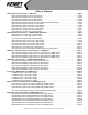
Table of Contents L-Wire Wound Chip Inductors - L-PW Series . . . . . . . . . . . . . . . . . . . . . . . . . . . . . . . . . . . . . . . . . . . . . . . . . . . Page 4 0805 Case Size Standard Type (L-PWS Series) . . . . . . . . . . . . . . . . . . . . . . . . . . . . . . . . . . . . . . . . . . . . Page 5 0806 Case Size Standard Type (L-PWS Series) . . . . . . . . . . . . . . . . . . . . . . . . . . . . . . . . . . . . . . . . . . . . Page 5 1007 Case Size Standard Type (L-PWS Series) . . . . . . . . . . .
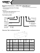
Wire Wound Chip Inductors - L-PWS/L-PWF/L-PWI/L-PWR Series Features: • Small size wound chip inductor with low DC resistance • Dimension without directional influence on mountability and characteristics Operating Temperature: • - ºC to +105ºC (including self-generated heat) Applications: • Digital Still Cameras (DSC), Digital Video Cameras (DVC), PDA’s and other portable digital equipment • Portable telephones and wireless LAN Part Numbering Table L C 0805 100 M PWS T Inductor Packaging Code Cas
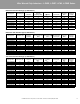
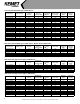
Wire Wound Chip Inductors - L-PWS, L-PWF, L-PWI, L-PWR Series 0805 Case Size Standard Type (L-PWS Series) Ordering Code Inductance (μH) Inductance Tolerance Minimum Self Resonant Frequency (MHz) DC Resistance Ω) (±30%) (Ω Maximum Rated Current (mA) Measuring Frequency (MHz) Tape & Reel Packaging Quantity L0805C1R0MPWST 1.0 ±20% 100 0.15 300 7.96 3,000 L0805C2R2MPWST 2.2 ±20% 80 0.23 240 7.96 3,000 L0805C4R7MPWST 4.7 ±20% 45 0.40 140 7.
1207 Case Size Standard Type (L-PWS Series) Ordering Code Inductance (μH) Inductance Tolerance Minimum Self Resonant Frequency (MHz) DC Resistance Ω) (±30%) (Ω Maximum Rated Current (mA) Measuring Frequency (MHz) Tape & Reel Packaging Quantity L1207C1R0MPWST L1207C1R5MPWST L1207C2R2MPWST L1207C3R3MPWST L1207C4R7MPWST L1207C6R8MPWST L1207C100(_)PWST L1207C150(_)PWST L1207C220(_)PWST L1207C330(_)PWST L1207C470(_)PWST L1207C680(_)PWST L1207C101(_)PWST L1207C151(_)PWST L1207C221(_)PWST L1207C331(_)PWST
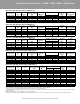
Wire Wound Chip Inductors - L-PWS, L-PWF, L-PWI, L-PWR Series 1007 Case Size High Current Type (L-PWI Series) Ordering Code L1007C1R0MPWIT L1007R1R0MPWIT* L1007C1R5MPWIT L1007C2R2MPWIT L1007C3R3MPWIT L1007C4R7MPWIT L1007C6R8MPWIT L1007C100MPWIT L1007C150MPWIT L1007C220MPWIT L1007C330MPWIT L1007C470MPWIT L1007C680MPWIT L1007C101MPWIT L1007C151MPWIT L1007C221MPWIT L1007C331MPWIT L1007C471MPWIT L1007C681MPWIT * Low Rdc Type Inductance (μH) Inductance Tolerance Minimum Self Resonant Frequency (MHz) DC Resi
Wire Wound Chip Inductors - L-DWS/L-DWI/L-DWL/L-DWF Series Features: • Small size wound chip inductor with high current • Dimension without directional influence on mountability and characteristics Operating Temperature: • - ºC to +105ºC (including self-generated heat) Applications: • Digital Still Cameras (DSC), Digital Video Cameras (DVC), PDA’s and other portable digital equipment • For DC-DC converter circuit Part Numbering Table L 0805 C 100 M DWS T Inductor Packaging Code Case Size (EIA) 0
Wire Wound Chip Inductors - L-DWS, L-DWI, L-DWL, L-DWF Series 0805 Case Size Standard Type (L-DWS Series) Ordering Code L0805C2R2MDWST L0805C4R7MDWST L0805R100MDWST L0805C220MDWST L0805C470MDWST Inductance (μH) Inductance Tolerance 2.2 4.7 10 22 47 ±20% ±20% ±20% ±20% ±20% Minimum Self Resonant Frequency (MHz) 80 45 32 16 11 DC Resistance Ω) (±30%) (Ω 0.23 0.40 0.50 1.70 3.70 Maximum Rated Current (mA) 1 410 300 200 135 90 2 770 580 520 280 190 Measuring Frequency (MHz) 7.96 7.96 2.52 2.52 2.
07 Case Size High Current Type (L-DWI Series) Ordering Code Inductance (μH) L1007C1R0MDWIT L1007C2R2MDWIT L1007C4R7MDWIT L1007C100MDWIT L1007C220MDWIT L1007C470MDWIT L1007C101MDWIT L1007C220MDWIT L1007C470MDWIT L1007C681MDWIT 1.0 2.2 4.7 10 22 47 100 220 470 680 Minimum Self Inductance Resonant Frequency Tolerance (MHz) ±20% ±20% ±20% ±20% ±20% ±20% ±20% ±20% ±20% ±20% 100 68 41 30 19 12 9 5.5 3.5 3 DC Resistance Ω) (±30%) (Ω 0.08 0.13 0.20 0.36 0.77 1.90 3.7 8.
Multilayer Chip Inductors - High Frequency - L-RMS Series Multilayer Chip Inductors for High Frequency - L-RMS Series Features: Operating Temperature: • Multilayer inductor made of advanced ceramics with low • 0201: -55ºC to +125ºC resistivity silver used as internal conductors, provides • 0402: -55ºC to +125ºC excellent Q and SRF characteristics & WR & • Multilayer block structure ensures outstanding reliability, • 0805: -40ºC to +85ºC high product
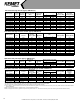
0201 Case Size Multilayer Chip Inductors for High Frequency (L-RMS Series) 12 Typical Q Self-resonant DC Resistance Ω) (Ω Frequency (MHz) Ordering Code Inductance (nH) Inductance Tolerance Q min. Measuring Frequency (MHz) Maximum Rated Current (mA) Thickness mm (inches) Tape & Reel Packaging Quantity 500 800 1000 min. typ. max. typ. L0201C1N0SRMST 1.0 ±0.3nH 4 100 6 12 17 22 27 10000 >13000 0.14 0.088 L0201C1N2SRMST 1.2 ±0.
Multilayer Chip Inductors - High Frequency - L-RMS Series 0402 Case Size Multilayer Chip Inductors for High Frequency (L-RMS Series) Ordering Code Measuring Inductance Inductance Q Frequency (nH) Tolerance min. (MHz) Typical Q Frequency (MHz) 100 300 500 800 1000 Self-resonant Frequency (MHz) DC Maximum Rated Current Resistance (mA) Ω) (Ω min. typ. Thickness mm (inches) Tape & Reel Packaging Quantity max. tvp. -55° to 125°C -55° to 85°C L0402C1N0SRMST 1.0 ±0.
0603 Case Size Multilayer Chip Inductors for High Frequency (L-RMS Series) 14 Typical Q Self-resonant Frequency (MHz) DC Resistance Ω) (Ω Maximum Tape & Reel Rated Thickness mm (inches) Packaging Current Quantity (mA) Ordering Code Inductance (nH) Inductance Tolerance Q min. Measuring Frequency (MHz) 100 300 500 800 1000 min. typ max. typ. L0603C1N0SRMST 1.0 ±0.3nH 8 100 14 30 40 70 90 10000 >13000 0.05 0.015 300 0.8 ±0.15 (0.031 ±0.006) 4,000 L0603C1N2SRMST 1.2 ±0.
Multilayer Chip Inductors - High Frequency - L-RMS Series 0805 Case Size Multilayer Chip Inductors for High Frequency (L-RMS Series) Typical Q Self-resonant DC Resistance Maximum Frequency Rated Ω) (Ω (MHz) Current (mA) min. typ. max. typ. Thickness mm (inches) Tape & Reel Packaging Quantity 300 0.85 ±0.2 (0.033 ±0.008) 4,000 300 0.85 ±0.2 (0.033 ±0.008) 4,000 0.03 300 0.85 ±0.2 (0.033 ±0.008) 4,000 0.10 0.03 300 0.85 ±0.2 (0.033 ±0.008) 4,000 >6000 0.13 0.04 300 0.85 ±0.2 (0.033 ±0.
Multilayer Chip Inductors - L-SMS/L-PMS/L-DMI Series Features: • Internal printed coil structure creates a closed magnetic circuit which acts as a magnetic shield eliminating crosstalk, thus permitting higher mounting densities.
Multilayer Chip Inductors - L-SMS, L-PMS, L-DMI Series 0402 Case Size Multilayer Chip Inductors (L-SMS Series) Minimum Self Resonant Q min. Frequency (MHz) Maximum DC Maximum Measuring Tape & Reel Resistance Rated Current Frequency Thickness mm (inches) Packaging Ω) (Ω (mA) (MHz) Quantity Ordering Code Inductance (μH) Inductance Tolerance L0402CR12(_)SMST 0.12 K±10%. M±20% 10 180 0.70 25 25 0.5 ±0.05 (0.02 ±0.002) 10,000 L0402CR15(_)SMST 0.15 K±10%. M±20% 10 165 0.90 25 25 0.5 ±0.
0603 Case Size Multilayer Chip Inductors (L-SMS Series) Maximum DC Minimum Self Maximum Measuring Resistance Rated Current Frequency Thickness mm (inches) Resonant Ω) (Ω Frequency (MHz) (mA) (MHz) Inductance (μH) Inductance Tolerance Q min. L0603C47NMSMST 0.047 ±20% 10 260 0.30 50 50 0.8 ±0.15 (0.031 ±0.006) 4,000 L0603C68NMSMST 0.068 ±20% 10 250 0.30 50 50 0.8 ±0.15 (0.031 ±0.006) 4,000 L0603C82NMSMST 0.082 ±20% 10 245 0.30 50 50 0.8 ±0.15 (0.031 ±0.
Multilayer Chip Inductors - L-SMS, L-PMS, L-DMI Series 0805 Case Size Multilayer Chip Inductors (L-SMS Series) Maximum DC Minimum Self Resistance Resonant Ω) (Ω Frequency (MHz) Maximum Measuring Rated Current Frequency (mA) (MHz) Tape & Reel Packaging Quantity Ordering Code Inductance (μH) Inductance Tolerance Q min. L0805C47NMSMST 0.047 ±20% 15 320 0.20 300 50 0.85 ±0.2 (0.033 ±0.008) 2,000 L0805C68NMSMST 0.068 ±20% 15 280 0.20 300 50 0.85 ±0.2 (0.033 ±0.
0603 Case Size Multilayer Chip Inductors (L-PMS Series) Ordering Code Inductance (μH) Minimum Inductance Inductance at Tolerance 200mA (μH) Maximum DC Resistance Ω) (Ω Maximum Rated Current (mA) Measuring Frequency (MHz) Thickness mm (inches) Tape & Reel Packaging Quantity L0603C4R7MPMST 4.7 ±20% 20 0.45 60 4 0.80 ±0.15 (0.031 ±0.006) 4,000 L0603C100MPMST 10.0 ±20% 20 0.85 50 2 0.80 ±0.15 (0.031 ±0.
Low Profile SMD Inductors - L-DWD Series Low Profile SMD Inductors (L-DWD Series) Features: • Small and low profile inductor • Corresponds to high current • Simple and original magnetic shield structure • Structure strong against shock-proof Part Numbering Table L Applications: • For small DC/DC converter; cellular phones, HDD, HVC, DSC, and PDA LCD display Operating Temperature: • -25ºC to +120ºC (including self-generated heat) 4012 C 100 M DWD T Inductor Case Size (EIA) Packaging Code T = Tape
Dimensions 4.0mm x 4.0mm (L-DWD4012 Type, 1.2mm Max. Height) Ordering Code Inductance (μH) Inductance Tolerance Measuring Frequency (KHz) Minimum Self-resonant Frequency (MHz) Maximum DC Resistance Ω) ±30% (Ω Maximum Rated Current (mA) Maximum Height (mm) Tape & Reel Packaging Quantity L4012C1R0NDWDT L4012C2R2MDWDT L4012C3R3MDWDT L4012C4R7MDWDT L4012C6R8MDWDT L4012C100MDWDT L4012C150MDWDT L4012C220MDWDT L4012C330MDWDT L4012C470MDWDT 1.0 2.2 3.3 4.7 6.
High Current Ferrite Chip Beads - Z-PWS, Z-PWZ Series High Current Ferrite Chip Beads - Z-PWS/Z-PWZ Series Features: • Power supply units: Large withstand voltage (allowable current up to 6A) Resistant to high energy High reliability • There are several variations of the standard (Z-PWS) type (10th digit in part number) “A” for broadband “B” for upper MHz range applications “G” for GHz range applications • The Z-PWZ type is optimal for circuit designs which require impedance and large currents to combat ra
0603 Case Size High Current Ferrite Chip Beads (Z-PWS Series) Maximum DC Maximum Rated Resistance Current (A) Ω) (Ω Ordering Code Impedance Ω) (Ω Measuring Frequency (MHz) Z0603C230BPWST 23 ±30% 100 0.007 Z0603C280APWST 28 ±30% 100 0.007 Thickness mm (inches) Tape & Reel Packaging Quantity 4 O.8 ±0.2 (0.031 ±0.008) 4,000 4 O.8 ±0.2 (0.031 ±0.
High Current Ferrite Chip Beads - Z-PWS, Z-PWZ Series 0603-1812 Case Size High Impedance Type Ferrite Chip Beads (Z-PWZ Series) Ordering Code EIA Case Size Impedance Ω) (Ω Measuring Frequency (MHz) Maximum DC Resistance Ω) (Ω Maximum Rated Current (A) Thickness mm (inches) Tape & Reel Packaging Quantity 0603 Case Size High Impedance Ferrite Chip Beads (Z-PWZ Series) Z0603C470BPWZT 0603 47 ±25% 100 0.02 3.5 0.8 ±0.1 (0.031 ±0.004) 4,000 Z0603C600BPWZT 0603 60 ±25% 100 0.025 3 0.8 ±0.
Multilayer Ferrite Chip Beads - Z-SMS/Z-PMS Series Z-SMS Features: • Internal silver printed layer creates a closed circuit which acts as a magnetic shield to minimize heat generation and crosstalk • No need for grounding provides greater circuit design flexibility • Several material types and a broad range of impedance values provide noise countermeasures for various applications (10th digit in part number) “A” Suppresses the XL component.
Multilayer Ferrite Chip Beads - Z-SMS, Z-PMS Series 0201 Multilayer Ferrite Chip Beads Standard Type (Z-SMS Series) Ordering Code Impedance Ω) ±25% (Ω Measuring Frequency (MHz) Maximum DC Resistance Ω) (Ω Maximum Rated Current (mA) Thickness mm (inches) Tape & Reel Packaging Quantity Z0201C220ASMST 22 100 0.10 500 0.30 ±0.03 (0.012 ±0.001) 15,000 Z0201C330ASMST 33 100 0.20 350 0.30 ±0.03 (0.012 ±0.001) 15,000 Z0201C800ASMST 80 100 0.40 200 0.30 ±0.03 (0.012 ±0.
0603 Multilayer Ferrite Chip Beads Standard Type (Z-SMS Series) Ordering Code Impedance Ω) ±25% (Ω Measuring Frequency (MHz) Maximum DC Ω) Resistance (Ω Maximum Rated Current (mA) Thickness mm (inches) Tape & Reel Packaging Quantity Z0603C121ESMST 120 100 0.15 600 0.80 ±0.15 (0.031 ±0.006) 4,000 Z0603C241ESMST 240 100 0.25 450 0.80 ±0.15 (0.031 ±0.006) 4,000 Z0603C431ESMST 430 100 0.30 400 0.80 ±0.15 (0.031 ±0.006) 4,000 Z0603C601ESMST 600 100 0.40 300 0.80 ±0.15 (0.031 ±0.
Multilayer Ferrite Chip Beads - Z-SMS, Z-PMS Series 0805 Multilayer Ferrite Chip Beads Standard Type (Z-SMS Series) Ordering Code Impedance Ω) ±25% (Ω Measuring Frequency (MHz) Maximum DC Ω) Resistance (Ω Maximum Rated Current (mA) Thickness mm (inches) Tape & Reel Packaging Quantity Z0805C150ASMST 15 100 0.05 1200 0.85 ±0.2 (0.033 ±0.008) 4,000 Z0805C220ASMST 22 100 0.05 1200 0.85 ±0.2 (0.033 ±0.008) 4,000 Z0805C330ASMST 33 100 0.05 1200 0.85 ±0.2 (0.033 ±0.
DISCLAIMER All electronic components or devices listed in this catalog are developed, designed and intended for use in general electronic equipment. Before incorporating these components into any equipment in the fields of aerospace, military or medical, where higher safety and reliability are required, please contact KEMET Corporation for more details.
World Sales Headquarters KEMET Electronics Corporation P.O. Box 5928 Greenville, SC 29606 Phone: 864-963-6300 Europe KEMET Electronics S.A. 15bis chemin des Mines 1202 Geneva, Switzerland Phone: 41-22-715-0100 Asia KEMET Electronics Marketing PTE Ltd. 73 Bukit Timah Road #05-01 Rex House Singapore, 229832, Singapore Phone: 65-6586-1900 KEMET Electronics Asia Ltd. 30 Canton Road, Room 1512 SilverCord Tower II Tsimshatshui, Kowloon Hong Kong Phone: 852-2305-1168 © KEMET Electronics Corporation, P.O.