
Datasheet


© KEMET Electronics Corporation • KEMET Tower • One East Broward Boulevard C1102_KPS-MCL_200C_STACKS • 3/31/2020
Fort Lauderdale, FL 33301 USA • 954-766-2800 • www.kemet.com
3
Surface Mount and Through-Hole Multilayer Ceramic Capacitors
KPS-MCL Low-Loss High Temperature 200°C SMPS Stacks, 200 – 2,000 VDC (Industrial Grade)
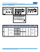
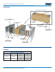
Dimensions – Inches (Millimeters)
Straight Lead (N)
E E C
Formed L Lead (L)Formed J Lead (J)
L
E
L
C
C
D
B
A
B
L
H K
G
F
J
D
A
B
H K
G
F
J
Straight Lead (N) Forme
d J (J) and L (L) Lead
LEAD ALIGNMENT
Note:
Lead alignment within pin rows
shall be 0.01” maximum.
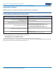
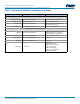
Case
Code
C
Lead Spacing
2
±0.025 (0.635)
E
Length
Number Of
Leads Per
Side
D Width
±0.025
(0.635)
A
Height
Maximum
B
Height
Maximum
H
Lead
Pitch
K
Lead
Width
F
Seating Plane
1
±0.010 (0.250)
Mounting
Technique
69
0.25
(6.35)
For
straight lead (N) and (J)
lead:
E = 0.30 (7.62) maximum
For
(L) lead:
E = 0.38 (9.65) maximum
3
0.32
(8.13)
0.21
(5.33)
0.29
(7.37)
0.1
(2.54)
0.02
(0.5)
For
straight lead (N),
seating plane
is 0.055"
For
(L) and (J) lead,
seating plane
is 0.070"
Solder
reow
only
5
0.53
(13.5)
10
1.06
(26.9)
70
3
0.32
(8.13)
0.26
(6.60)
0.34
(8.64)
5
0.53
(13.5)
10
1.06
(26.9)
1
Seating plane is the distance between the circuit board and the bottom of the lowest capacitor in the stack.
2
Lead spacing dimension from outside of lead frame.