
Datasheet


© KEMET Electronics Corporation • KEMET Tower • One East Broward Boulevard C1102_KPS-MCL_200C_STACKS • 3/31/2020
Fort Lauderdale, FL 33301 USA • 954-766-2800 • www.kemet.com
2
Surface Mount and Through-Hole Multilayer Ceramic Capacitors
KPS-MCL Low-Loss High Temperature 200°C SMPS Stacks, 200 – 2,000 VDC (Industrial Grade)
Applications
• Industrial
• Down-hole
• Defense and aerospace
• Hybrid and Electric Vehicles (HEVs, BEVs)
• SMPS
• Input and output ltering on power supplies,
often found on “capacitor banks“
• Snubber circuits and DC link
• Resonator circuits
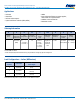
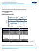
Ordering Information
L1 G N 69 C 224 K A 03
Product
Family
Dielectric
Classication/
Characteristic
Lead
Conguration
1
Case Size/
Case Code (CC)
Rated
Voltage
(DC)
Capacitance
Code (pF)
Capacitance
Tolerance
Lead/
Termination
Finish
2
Number
of Chips
L1 G =
200°C C0G
(BME)
N = Straight
pin
L = Formed "L"
J = Formed "J"
69
70
2 = 200 V
C = 500 V
B = 630 V
D = 1,000 V
F = 1,500 V
G = 2,000 V
Two
Signicant
Digits and
number of
zeros
J = ±5%
K = ±10%
A = Silver
H = Solder
Coated (60/40)
03 – 3 Chips
05 – 5 Chips
10 – 10 Chips
1
Lead conguration and dimension details are outlined in the "Dimensions" section of this document. Additional lead congurations may be available.
Contact KEMET for details.
2
Solder coated (60/40) lead termination nish (H) only available for Straight pin (N) lead conguration.
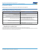
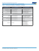
Lead Congurations – Inches (Millimeters)
Lead Style
Symbol
Lead Style
L
Lead Length
N (N) Straight
0.250 minimum
(6.35)
L (L) Formed
0.055±0.005
(1.4±0.13)
J (J) Formed
0.055±0.005
(1.4±0.13)
Additional lead congurations may be available. Contact KEMET for details.