Master M 358 Operating manual - EN Master M 358 © Kemppi 1 1921980 / 2242
Master M 358 Operating manual - EN CONTENTS 4 1. General 1.1 Equipment description 5 1.2 Master M 358 device 7 1.2.1 Wire feed mechanism 9 1.2.2 Control panel 9 1.3 Master M Cooler cooling unit (optional) 11 12 2. Installation 2.1 Installing power source mains plug 13 2.2 Installing cooling unit (optional) 14 2.3 Installing equipment on cart (optional) 16 2.4 Connecting welding gun 18 2.5 Installing earth return cable 19 2.6 Installing remote control (optional) 20 2.
Master M 358 Operating manual - EN 3.4.4 WisePenetration+ feature 57 3.4.5 WiseSteel feature 58 59 3.5 Pulse welding 3.5.1 MAX Cool process 59 3.5.2 MAX Position process 60 3.5.3 MAX Speed process 60 3.6 Wireless connection (WLAN) 61 3.6.1 Digital Welding Procedure Specification (dWPS) 62 3.6.2 WeldEye ArcVision 62 3.6.3 WeldEye with DCM 63 3.6.4 USB backup and restore 64 3.6.5 USB update 64 3.7 Using remote control 66 3.8 Changing welding polarity 67 3.
Master M 358 Operating manual - EN 1. GENERAL These instructions describe the use of Kemppi's Master M 358 welding equipment designed for both normal and pulsed MIG/MAG welding. Master M 358 is designed to be used together with Kemppi's Flexlite GX MIG welding guns with euro connector. Master M 358 can be used also for TIG * and MMA ** welding. * TIG welding requires the use of a dedicated Flexlite TX TIG torch with euro connector. ** MMA welding requires a dedicated DIX-euro adapter.
Master M 358 Operating manual - EN 1.1 Equipment description Master M 358 device models (350 A) • • Master M 358 G >> Generator-compatible >> Pulse device with automatic 1-MIG and pulse processes. Advanced MAX processes as optional. Master M 358 GM >> Generator-compatible and multi-voltage >> Pulse device with automatic 1-MIG and pulse processes. Advanced MAX processes as optional. Both Master M 358 device models have a 4-roll wire feed mechanism with the maximum wire spool diameter of 300 mm.
Master M 358 Operating manual - EN For more information on optional accessories, contact your local Kemppi dealer. EQUIPMENT IDENTIFICATION Serial number Serial number of the device is marked on the rating plate or in another distinctive location on the device. It is important to make correct reference to the serial number of the product when ordering spare parts or making repairs for example.
Master M 358 Operating manual - EN 1.2 Master M 358 device Front 1. 2. 3. 4. 5. 6. 7. 8. 9.
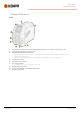
Master M 358 Operating manual - EN Rear 1. 2. 3. 4. Shielding gas hose connector. Mains cable Power switch Rear locking interface >> For locking on top of the cooling unit or on a cart. Inside wire feed cabinet 1. 2. 3. 4. 5. 6. © Kemppi Rotameter for gas Polarity terminals Wire inch button >> Drive the filler wire forward (with arc off) Gas test button >> Test the shielding gas flow and flush the gas line Wire feed mechanism (refer to "Wire feed mechanism" on the next page) Wire spool.
Master M 358 Operating manual - EN 1.2.1 Wire feed mechanism 1. 2. 3. 4. 5. 6. 7. 8. Drive rolls and drive roll mounting caps Middle guide tube locking clip Middle guide tube Inlet guide tube Pressure handles Pressure rolls and pressure roll mounting pins Pressure roll locking arms Outlet guide tube. For replacing the feed rolls, refer to "Installing and replacing feed rolls" on page 21. For replacing the wire guide tubes, refer to "Installing and replacing wire guide tubes" on page 23. 1.2.
Master M 358 Operating manual - EN For using the control panel, refer to "Using control panel" on page 36.
Master M 358 Operating manual - EN 1.3 Master M Cooler cooling unit (optional) Front 1. 2. 3. 4. 5. 6. 7. Cooler container cap Cooling liquid level indicator Cooling liquid circulation button >> Keeping the button pressed activates the pump and circulates the cooling liquid throughout the system. Once released, the pump stops. Front locking interface >> For locking on the cart Front locking interface >> For locking to the power source Coolant inlet connector (red) Coolant outlet connector (blue).
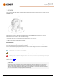
Master M 358 Operating manual - EN 2. INSTALLATION Do not connect the equipment to the mains before the installation is complete. Do not modify the welding equipment in any way, except for the changes and adjustments covered in the manufacturer’s instructions. Place the machine on a horizontal, stable and clean ground. Protect the machine from rain and direct sunshine. Check that there is enough space for cooling air circulation in the machine vicinity.
Master M 358 Operating manual - EN 2.1 Installing power source mains plug Only an authorized electrician is allowed to install the mains cable and plug. Do not connect the machine to the mains before the installation is complete. Install the 3-phase plug according to the Master M device and site requirements. The mains cable includes the following wires: 1. 2. 3. 4.
Master M 358 Operating manual - EN 2.2 Installing cooling unit (optional) The Master M cooling unit must be installed by authorized service personnel. Tools needed: 1. Remove the small connector cover in the rear of the power source. 2. Route the cooling unit's connection cables so that they remain accessible through the next steps. 3. Lift the Master M device on top of the cooling unit so that the fixing plates align and go into their slots.
Master M 358 Operating manual - EN 4. Fix the units together with two screws (M5x12) in the front and two screws (M5x12) in the rear. 5. Connect the cooling unit cables. 6. Replace the small connector cover.
Master M 358 Operating manual - EN 2.3 Installing equipment on cart (optional) Master M has four transport unit options: a 4-wheel cart with a gas bottle rack (P45MT), a 4-wheel cart without a gas bottle rack (P43MT), a 2-wheel cart with a gas bottle rack (T25MT) and a 2-wheel cart without a gas bottle rack (T35A). The equipment installation principle and the bottom securing interface is the same with all carts. Tools needed: 1. Install the cooling unit on the cart. 2.
Master M 358 Operating manual - EN T35A 2-wheel cart: The cart must be in horizontal position during welding. For lifting the Master M equipment, refer to "Lifting equipment" on page 69.
Master M 358 Operating manual - EN 2.4 Connecting welding gun Master M is designed to be used with the Kemppi Flexlite GX welding guns. For the Flexlite GX operating instructions, refer to userdoc.kemppi.com. Always check that the wire liner, contact tip and gas nozzle are suitable for the job. 1. Push the welding gun connector into the euro connector and hand-tighten the collar. 2. If your setup includes a water-cooled gun, connect the cooling liquid hoses to the cooling unit. The hoses are colorcoded.
Master M 358 Operating manual - EN 2.5 Installing earth return cable 1. Connect the earth return cable to the Master M machine's earth return cable connector.
Master M 358 Operating manual - EN 2.6 Installing remote control (optional) Remote controls are optional. To enable remote operation, connect the remote control device to the Master M welding equipment. The remote control mode can be set and adjusted in the control panel settings ("Control panel: Device settings" on page 51). When the Remote mode is selected in the settings and both wireless and wired remotes are connected, the wired remote will be used. Remote control HR43/HR40 1.
Master M 358 Operating manual - EN 2.7 Installing and replacing feed rolls Replace the feed rolls when the filler wire diameter or material changes. Select the feed rolls according to the tables in "Wire feeder consumables" on page 88. 1. Open the wire feed cabinet hatch. 2. Release the pressure handles on the wire feed mechanism. 3. Open the locking arms to release the feed rolls. 4. Pull the pressure roll mounting pins and drive roll mounting caps off.
Master M 358 Operating manual - EN The pressure rolls' mounting pins have central axles attached to them, whereas the drive rolls' central axles act as drive shafts attached directly to the wire feed mechanism/motor. 5. Remove the drive rolls and pressure rolls. 6. Follow the previous steps in reverse to install the wire feed rolls. Align the cut on the drive rolls' bottom with the pin on the drive shaft. 7.
Master M 358 Operating manual - EN 2.8 Installing and replacing wire guide tubes The wire feed mechanism includes three wire guide tubes. Replace them when the filler wire diameter or material changes. Select the wire guide tubes according to the tables in "Wire feeder consumables" on page 88. When replacing the outlet guide tube, the welding gun must be detached. a. b. c. Inlet guide tube Middle guide tube Outlet guide tube To replace the wire guide tubes: 1.
Master M 358 Operating manual - EN 2.9 Installing and changing wire Always ensure that the feed rolls are suitable for the filler wire (diameter and material) in question. For more information, refer to "Wire feeder consumables" on page 88. Install the welding gun to the Master M device before installing the wire spool. When changing the wire spool, remove the remaining filler wire from the welding gun and wire feed mechanism before removing the wire spool. To remove the wire spool: 1.
Master M 358 Operating manual - EN 2. If needed, adjust the spool brake by turning the spool brake tightening knob in the center of the spool hub. To install the filler wire: 1. Release the filler wire end from the spool and cut off any deformed section so that the end is straight. Ensure that the filler wire does not spill from the spool when it is released. 2. File the tip of the filler wire smooth. Sharp edges on the filler wire tip may damage the wire liner. 3.
Master M 358 Operating manual - EN 4. Guide the filler wire through the inlet guide tube (a) and middle guide tube (b) and into the outlet guide tube (c), which feeds the filler wire to the welding gun. 5. Push the filler wire by hand into the gun so that the wire reaches the wire liner. 6. Close the pressure arms so that the filler wire is locked between the feed rolls.
Master M 358 Operating manual - EN 7. Adjust the pressure of the feed rolls with the pressure adjustment wheels. The pressure is the same for both feed roll pairs. The graduated scales on the pressure handle indicate the pressure applied to the feed rolls. Adjust the pressure of the feed rolls according to the table below. Filler wire material Feed roll profile* Filler wire diameter (mm) Adjustment (x100N) Fe/Ss solid V-groove 0.8-1.0 1.5-2.0 ≥ 1.2 2.0−2.5 MC/FC V-groove, knurled ≥ 1.2 1.0−2.
Master M 358 Operating manual - EN 9. Before welding, ensure that the welding parameters and settings conform to your welding setup.
Master M 358 Operating manual - EN 2.10 Installing gas bottle and testing gas flow Handle gas bottles with care. There is a risk of injury if the gas bottle or the bottle valve is damaged! Always secure the gas bottle properly in an upright position to a special holder on the wall or on the welding equipment cart. Always keep the gas bottle valve closed when not welding. - If a transport unit with a gas bottle rack is used, install the gas bottle on the transport unit first, then make the connections.
Master M 358 Operating manual - EN 3. If not already, connect the welding gun to the device (refer to "Connecting welding gun" on page 18). 4. Connect the gas hose to the welding device. 5. Open the gas bottle valve. 6. Press the gas test button (*) to test and adjust the gas flow. Use either the built-in rotameter or an external flow meter and regulator for measuring and adjustment. The gas test time is 20 seconds by default. The time can be changed in the control panel.
Master M 358 Operating manual - EN 2.11 How to get welding programs The Master M 358 device comes with a welding program work pack preinstalled. These work pack versions cover the basic welding tasks with the automatic 1-MIG and pulsed welding process. The additional welding programs, Wise features (WiseSteel, WiseFusion, WisePenetration+) and MAX processes (MAX Cool, MAX Position, MAX Speed) are installed at the time of purchase according to your specific welding requirements.
Master M 358 Operating manual - EN 3. OPERATION Before using the equipment, ensure that all the necessary installation actions have been completed according to your equipment setup and instructions. Welding is forbidden in places where there is an immediate fire or explosion hazard! The wire feed cabinet hatch must be kept closed when welding. Check that there is enough space for cooling air circulation in the machine vicinity.
Master M 358 Operating manual - EN 3.1 Preparing welding system for use Before starting the use of the welding equipment: • • • • • Ensure the installation has been completed Switch the welding equipment on Prepare the cooler Connect the earth return cable Calibrate the welding cable (in MIG operation mode only) >> Refer to "Calibrating welding cable" on page 35 for instructions. Turning on welding system To turn on the welding equipment, turn the power source main switch to ON (I).
Master M 358 Operating manual - EN 1. Open the cooler cap. 2. Fill the cooler with coolant. Do not fill over the max. marking. 3. Close the cooler cap. To circulate the coolant: Press the coolant circulation button in the cooler front panel (*). It activates the motor, which pumps the coolant to the hoses and to the welding gun. Complete the coolant circulation operation after each time you change the welding gun.
Master M 358 Operating manual - EN 3.2 Calibrating welding cable The welding cable resistance can be measured using the built-in cable calibration function without an additional measurement cable. This calibration function is available only in MIG operation mode. 1. Connect the earth return cable between the welding device and work piece. 2. Remove the welding gun gas nozzle. 3. Connect the welding gun to the welding device. 4. Turn the welding device on. 5.
Master M 358 Operating manual - EN 3.3 Using control panel The Master M 358 control panel includes advanced features and functions for MIG welding with the option to use Master M 358 also for TIG (DC) and MMA welding. The automatic 1-MIG process is available along with the Kemppi welding programs as well as Wise features and MAX processes (optional). For more information, refer to "How to get welding programs" on page 31. General 1. 2. 3. 4. 5. 6.
Master M 358 Operating manual - EN Views (7) A. B. C. D. E. F. G. H. I. Home view Weld Assist view Memory channels view WPS view Welding parameters view Weld history view Device settings view WLAN view Info view After each weld, a weld summary (Weld data) is displayed briefly. 3.3.1 Control panel: Home view Master M 358 control panel's Home view is also the main welding view. 1. 2. 3. 4. 5. 6. 7. 8. 9.
Master M 358 Operating manual - EN • • • Pulse MIG: Wire feed speed adjustment DPulse MIG: Wire feed speed adjustment and switching between pulse levels with control knob button TIG/MMA: Welding current adjustment Right control knob: • • • • • Manual MIG: Welding voltage adjustment 1-MIG: Fine tuning of welding voltage or Wise/MAX parameter adjustment Pulse MIG: Fine tuning of welding voltage or Wise/MAX parameter adjustment DPulse MIG: Fine tuning of welding voltage MMA: Dynamics adjustment.
Master M 358 Operating manual - EN 3. Weld Assist gives you a recommendation for these welding parameters: >> >> >> >> >> Welding process Wire feed speed Gas flow rate Travel speed Separate values for root and fill passes (where applicable). 4. Confirm the Weld Assist’s recommendation for welding settings by selecting 'Save'. 5. Select the memory channel slot for saving. 6. Once saved, the memory channel can be taken into use by selecting Use in Weld Assist, or later in the Memory channels view.
Master M 358 Operating manual - EN The amount of available memory channels differs between different operation modes: MIG (100 channels), TIG (10 channels) and MMA (10 channels). The operation mode set in the control panel Settings determines for which main welding process the memory channels are shown. Changing memory channel Turn the right control knob to highlight the desired memory channel. The highlighted memory channel is automatically activated.
Master M 358 Operating manual - EN Tip: Changed welding parameters can be quickly saved onto the active memory channel by keeping the Memory channels button pressed for approx. 2 seconds. This works in any view. 3.3.4 Control panel: WPS view The use of digital WPS (Welding Procedure Specification, dWPS) and WeldEye cloud service require a valid Kemppi WeldEye subscription with the Welding Procedures module.
Master M 358 Operating manual - EN 1. Select the desired dWPS for viewing and for selecting a weld pass by turning the right control knob and pressing the right control knob button. If a dWPS and weld pass have already before been linked to the active memory channel, the WPS view opens directly to that WPS. To open the list of available dWPSs, select 'Change WPS'. 2. Select a weld pass on the dWPS by turning the right control knob and enter the actions menu by pressing the right control knob button.
Master M 358 Operating manual - EN 3. If a memory channel has been already linked to the weld pass, you can activate the selected weld pass and the default memory channel by selecting 'Activate'. 4. If a memory channel has not been linked to the weld pass previously, you can link the weld pass to an existing memory channel ('Select linked channel'). A memory channel can also be linked to a weld pass on a dWPS through the Memory channels view by selecting 'Link to WPS' in the memory channel's actions menu.
Master M 358 Operating manual - EN 3.3.5 Control panel: Welding parameters The Welding parameters view includes a start and stop curve for adjusting the most essential parameters for a weld. The bottom section of the view lists the available adjustments for the selected welding process. The welding process selection is based on the active memory channel and its settings. Many of the welding parameters are welding process specific and are visible and available for adjustment accordingly.
Master M 358 Operating manual - EN Welding parameters and feature descriptions MIG and 1-MIG welding parameters The parameters listed here are available for adjustment with the MIG and 1-MIG processes. Parameter Parameter value Description Process MIG, 1-MIG, Pulse, DPulse, MAX Cool, MAX Speed, MAX Position This MIG welding process selection depends on the active welding program. For more information on the additional processes, refer to "Additional guidance to functions and features" on page 56.
Master M 358 Operating manual - EN Dynamics -10.0 ... +10.0, step 0.2 Default = 0 Controls the short circuit behavior of the arc. The lower the value the softer the arc, the higher the value the rougher the arc. (Not available with MAX Cool and MAX Speed.) Crater fill ON/OFF - Crater fill time 0.1 ... 10.0 s, Auto, step 0.1 Default = 1.0 s - Crater fill wire feed speed 0.70 ... 25.0 m/min, Auto, step 0.05 or 0.1 Default = 5 m/min - Crater fill voltage 8 ... 45 V, Auto, step 0.
Master M 358 Operating manual - EN 1-MIG welding parameters The parameters listed here are available for adjustment only with the 1-MIG process. Parameter Parameter value Description Trigger logic 2T, 4T, Powerlog (2 levels or 3 levels) Welding guns can have several alternative trigger operation modes (trigger logics). Most common are 2T and 4T. In 2T mode you hold the trigger down while welding. In 4T mode you press and release the trigger to start or to stop welding.
Master M 358 Operating manual - EN Pulse/DPulse welding parameters The parameters listed here are available for adjustment in addition to the MIG and 1-MIG welding parameters. Parameter Parameter value Description Pulse current % -10 ... +15 %, step 1 The pulse current fine tuning relative to the current with Pulse and DPulse welding processes. DPulse ratio 10 ... 90 %, step 1 This adjusts the double pulse time percentage, i.e. how long the double pulse is at the first pulse level.
Master M 358 Operating manual - EN MAX Position parameters The parameters listed here are MAX Position process specific. Parameter Parameter value Description MAX Position frequency -0.5 ... +0.5 Hz, step 0.1 Default = 0 MAX Position frequency fine tuning. Pulse current % -10 … 15 %, step 1 Default = 0 MAX Position pulse current adjustment. Plate thickness 3.0 ... 12.0 mm MAX Position plate thickness setting.
Master M 358 Operating manual - EN 3.3.6 Control panel: Weld history The Weld history view collects the information of the past welds (the last 10) into one view for later checking. To change how the weld data averages are calculated (with or without slope phases) refer to "Control panel: Device settings" on the next page. Heat input calculation in weld history view The heat input of a weld can be calculated by entering the weld length into the weld's history entry. 1.
Master M 358 Operating manual - EN 3.3.8 Control panel: Device settings Changing settings 1. Turn the right control knob to highlight the desired settings parameter. 2. Press the right control knob to select the settings parameter for adjustment. 3. Turn the right control knob to select the settings value. >> Depending on the settings parameter to be adjusted, refer also to the Settings table below for more details. 4.
Master M 358 Operating manual - EN Remote control OFF/Remote/Gun Default = OFF If remote controller is not connected, this selection is not available. Remote mode (with 1-knob remote control) Wire feed speed / Channel This determines what is changed with the remote, wire feed speed or memory channel (available channels: 1...5). If remote controller is not connected and remote not selected, this selection is not available.
Master M 358 Operating manual - EN Weld data average Without slopes / Entire weld Default = Without slopes This feature allows the user to change how the weld data averages are calculated: with or without the slope phases in the beginning and in the end of the weld. This setting affects the calculation of the averages for the following: welding voltage (terminal and arc voltage), welding current, welding power and wire feed speed. Brightness 1...10 The control panel display brightness.
Master M 358 Operating manual - EN 1. Go to the Memory channels view. (Refer to "Control panel: Channels" on page 39 for more information.) 2. Enter the actions menu. 3. Select Create channel. >> A filter view opens. 4. Use the filter options (e.g. material, wire material or wire diameter) to find the welding programs best suited for the purpose. The operation mode set in the panel Settings determines for which main welding process the programs here are shown.
Master M 358 Operating manual - EN 7. To save, scroll down to Save to and select it. Select the memory channel slot for saving and confirm. Once ready, you can continue to the Welding parameters view to adjust the welding settings for the new channel, create a new channel or go back to the Channels view. Tip: It is also possible to create new channels based on all of the unused welding programs available for the selected operation mode by selecting Create all in the Channel view's actions menu.
Master M 358 Operating manual - EN 3.4 Additional guidance to functions and features This section summarizes the Master M 358 functions and features and how to use them. 3.4.1 Trigger logic functions You can select the trigger logic in the Welding parameters view. 2T In 2T, pressing the trigger ignites the arc. Releasing the trigger switches the arc off. 4T In 4T, pressing the trigger starts the pre gas, and releasing the trigger ignites the arc. Pressing the trigger again switches the arc off.
Master M 358 Operating manual - EN Powerlog trigger logic is not available with manual MIG, MAX Speed, MAX Position or DPulse processes. Powerlog trigger logic cannot be used together with a remote control. If a Powerlog memory channel is selected when a remote control is in use, the trigger logic is automatically switched to 4T. 3.4.2 1-MIG 1-MIG is a MIG/MAG welding process where the voltage is defined automatically when you adjust the wire feed speed.
Master M 358 Operating manual - EN the arc focused and optimally short. WisePenetration+ enables welding with Reduced Gap Technology (RGT) and is compatible with 1-MIG welding process. >> To take WisePenetration+ into use, go to the control panel's Welding parameters view and apply the WisePenetration+ feature. >> To adjust the welding current while welding, in the control panel's Home view, turn the left control knob.
Master M 358 Operating manual - EN 3.5 Pulse welding The advantages of Pulse are a higher welding speed and deposition rate compared to short-arc welding, lower heat input compared to spray-arc welding, a spatter-free globular arc and smooth appearance of the weld. Pulse is suitable for all position welding. It is excellent for welding aluminum and stainless steel, especially when the material thickness is small.
Master M 358 Operating manual - EN • • CuSi3 & Ar (1.0 mm) CuAl8 & Ar (1.0 mm). 3.5.2 MAX Position process MAX Position is a synergic MIG/MAG welding process optimized for vertical fillet welds (position: PF). MAX Position automatically switches between two separate power levels. The two power levels can use the same welding process or two different welding processes. >> To take MAX Position into use, go to the control panel's Welding parameters view and apply MAX Position.
Master M 358 Operating manual - EN 3.6 Wireless connection (WLAN) To connect the welding equipment to your local wireless network: 1. On the control panel, go to the WLAN view. 2. Turn the WLAN feature on by turning and pressing the right control knob. 3. Enter your local wireless network's SSID (Service Set Identifier), i.e. the name of your Wi-Fi network. >> Use the right control knob to select letters. 4. Enter your WLAN password. >> Use the right control knob to select letters.
Master M 358 Operating manual - EN The WLAN mode is set to 'Client' by default and it cannot be changed. 3.6.1 Digital Welding Procedure Specification (dWPS) The use of digital WPS (Welding Procedure Specification, dWPS) and WeldEye cloud service require a valid Kemppi WeldEye subscription with the Welding Procedures module. For more information on WeldEye, refer to weldeye.com or contact your Kemppi representative.
Master M 358 Operating manual - EN 1. On the Master M 358 control panel, go to the WPS view. 2. Use a QR code reader on your mobile device to open the WeldEye web link or navigate to 'https://register.weldeye.io/weldeye' on your web browser. 3. Complete the registration process as instructed on the registration page. Once finished, the equipment is connected to WeldEye ArcVision. You will be required to fill in the serial number and four-digit security pin of your Master M 358 machine.
Master M 358 Operating manual - EN WeldEye's modular structure is based on various useful functions that serve the needs of wide-ranging industries and welding-related tasks: • • • • Welding procedures >> Includes the digital library and management of pWPS, WPQR and WPS templates according to the most important welding standards. Personnel and qualifications >> Includes the management and renewal processes of all personnel - welders and inspectors - qualification certificates.
Master M 358 Operating manual - EN There can be only one ZIP file on the USB memory stick inserted into the welding system at once. This can be either a dedicated firmware pack for this welding system or a welding program and license pack (matching the power source serial number). For more information on the available software and compatibility, contact your local Kemppi representative. Firmware and welding software 1.
Master M 358 Operating manual - EN 3.7 Using remote control Remote control HR43 To adjust the wire feed speed, turn the knob on the remote control. To change the memory channel instead of the wire feed speed with the remote, change the remote mode setting in the "Control panel: Device settings" on page 51. Remote control HR40 To adjust the welding parameters, turn the knobs on the remote control.
Master M 358 Operating manual - EN 3.8 Changing welding polarity Welding polarity needs to changed for TIG welding. Also, some filler wires require changing the welding polarity. Check the recommended welding polarity on the filler wire package. Before handling electrical parts, ensure the welding device is disconnected from the mains. Tools needed: 17 mm 1. Turn off the welding device and disconnect it from the mains. 2. Open the wire feed cabinet hatch. 3.
Master M 358 Operating manual - EN 5. Connect the cables to the polarity terminals according to the polarity recommendation. 6. Replace the washers and bolts. Tighten to 17 Nm torque. 7. Replace the protective rubber covers.
Master M 358 Operating manual - EN 3.9 Lifting equipment If a gas bottle is installed on cart, DO NOT attempt to lift the cart with the gas bottle in place. 4-wheel cart: 1. Ensure that the welding equipment is properly secured to the cart. 2. Connect the 4-legged chain or straps from the hoist hook to the four lifting points on the cart on both sides of the welding equipment. 2-wheel cart (T25MT only): 1. Ensure that the welding equipment is properly secured to the cart. 2.
Master M 358 Operating manual - EN 4. MAINTENANCE When considering and planning routine maintenance, consider the operating frequency of the welding system and the working environment. Correct operating of the welding machine and regular maintenance helps you avoid unnecessary downtime and equipment failure.
Master M 358 Operating manual - EN 4.1 Daily maintenance Disconnect the power source from the mains before handling electrical cables. Welding machine maintenance Follow these maintenance procedures to maintain the proper functioning of the welding machine: • • • Check that all covers and components are intact. Check all the cables and connectors. Do not use them if they are damaged and contact service for replacements. Check the wire feed rolls and the pressure handle.
Master M 358 Operating manual - EN 4.2 Periodic maintenance Only qualified service personnel is allowed to carry out periodic maintenance. Only an authorized electrician is allowed to carry out electrical work. Before removing the cover plate, disconnect the power source from the mains and wait for about 2 minutes before discharging the capacitor. Check the electric connectors of the unit at least every six months. Clean oxidized parts and tighten loose connectors.
Master M 358 Operating manual - EN 4.3 Service workshops Kemppi Service Workshops complete the welding system maintenance according to the Kemppi service agreement.
Master M 358 Operating manual - EN 4.4 Troubleshooting The problems listed and the possible causes are not definitive, but suggest some typical situations that may turn up during normal use of the welding system. Welding device: Problem Recommended actions The welding device does not power up Check that the mains cable is plugged in properly. Check that the mains switch of the power source is at the ON position. Check that the mains power distribution is on.
Master M 358 Operating manual - EN Dirty and/or poor quality weld Check that the shielding gas has not run out. Check that the shielding gas flow is unobstructed. Check that the gas type is correct for the application. Check the polarity of the gun/electrode. Check that the welding procedure is correct for the application. Varying welding performance Check that the wire feed mechanism is adjusted properly. Blow compressed air through the wire liner to check that it is not blocked.
Master M 358 Operating manual - EN 4.5 Error codes In error situations, the control panel displays the number, title and possible cause of the error, and a proposed action to fix the issue. Error Code Title Possible cause Proposed action 1 Power source not calibrated Power source calibration has been lost. Restart the power source. If problem persists, contact Kemppi service. 2 Too low mains voltage Voltage in mains network is too low. Restart the power source.
Master M 358 Operating manual - EN 40 VRD error Open circuit voltage exceeds the VRD limit. Restart the power source. If problem persists, contact Kemppi service. 42 High current in wire feeder motor There may be too much pressure in the wire feed rolls or dirt in the wire line. Adjust the feed roll pressure. Clean the wire line. Change worn parts in the welding gun. 43 Overcurrent in wire feeder motor There may be too much pressure in the wire feed rolls or dirt in the wire line.
Master M 358 Operating manual - EN 4.6 Installing and cleaning power source air filter (optional) An optional power source air filter can be purchased separately. The air filter comes with a fixed casing designed to be mounted directly onto the power source air intake. Using the optional air filter decreases the rated power levels of the power source as follows (output 40 °C): 60% >>> 45% and 100% >>> 100%-20A. This is due to the slightly reduced cooling air intake.
Master M 358 Operating manual - EN Cleansing 1. Remove the air filter from the power source by releasing the clips on the edge of the air filter casing. 2. Blow the air filter clean with compressed air.
Master M 358 Operating manual - EN 4.
Master M 358 Operating manual - EN 5. TECHNICAL DATA Technical data: • • For Master M 358 device technical data, refer to "Master M 358 device" on the next page. For Master M Cooler cooling unit technical data, refer to "Master M cooling unit" on page 86. Additional information: • • • © Kemppi For ordering information, refer to "Master M 358 ordering info" on page 87. For wire feeder consumable information, refer to "Wire feeder consumables" on page 88.
Master M 358 Operating manual - EN 5.1 Master M 358 device Master M 358 G Master M 358 358 G Feature Value Mains connection voltage 3~50 Hz 380...460 V ±10 % Mains connection cable HO7RN-F 4 mm² Input power at rated maximum current 14 kVA Maximum supply current I1max @ 380...460 V Effective supply current I1eff @ 380...460 V I1eff 13.5 ... 10.
Master M 358 Operating manual - EN Al 0.8 ... 1.2 mm Wire feed speed 0.5 ... 25 m/min Maximum wire spool weight 20 kg Maximum wire spool diameter 300 mm Maximum shielding gas pressure 0.5 MPa Control panel Built-in Degree of protection 5.
Master M 358 Operating manual - EN No-load state power consumption No-load voltage MMA (power save) @ 400 V 20 W MMA (fans ON) @ 400 V 120 W @ 220...230 V U0 54 ... 56 V @ 380...460 V U0 55 ... 69 V Uav 53 ... 64V Open circuit voltage VRD voltage MMA 24 V Fuse Slow 32 A (220...230 V) 16 A ( 380...460 V) Output at +40 °C 40 % 380...460 V 220...230 V 350 A (MMA 330 A) 300 A (MMA 280 A) 60 % 380...460 V 220...230 V 280 A 240 A 100 % 380...460 V 220...230 V 220 A 190 A MIG 380...
Master M 358 Operating manual - EN Degree of protection IP23S External dimensions LxWxH 602 x 298 x 447 mm Package external dimensions LxWxH 610 x 300 x 445 mm, with cooler 700 mm Weight 27 kg Voltage supply for auxiliary devices 12 V Voltage supply for cooling unit Recommended minimum generator power @ 400 V 380...460 V 220...230 V 24 V 24 V Sgen 20 kVA Wired communication type CAN Wireless communication type Internal wireless module WUBT-236ACN(BT) - Wi-Fi standard IEEE 802.
Master M 358 Operating manual - EN 5.2 Master M cooling unit Master M Cooler Master M Cooler Feature Value Supply voltage Maximum supply current @ 380...460 V Cooling power @ 1 l/min U1 380...460 V +/- 10 % I1max 0.7 A 1.0 kW Recommended coolant MGP 4456 (Kemppi mixture) Maximum coolant pressure 0.4 MPa Tank volume 3l Operating temperature range With recommended coolant -20...+40 °C Storage temperature range -40...
Master M 358 Operating manual - EN 5.3 Master M 358 ordering info For Master M 358 ordering information and optional accessories, refer to Kemppi.com.
Master M 358 Operating manual - EN 5.4 Wire feeder consumables This section lists the feed rolls and wire guide tubes available both separately and in consumable kits. The consumable kits contain recommended feed roll and wire guide tube combinations for selected filler wire materials and diameters. The wire feeder consumables can be ordered in Configurator.kemppi.com. In the tables, standard refers to plastic feed rolls and heavy-duty refers to metal feed rolls.
Master M 358 Operating manual - EN Feed rolls The table below lists the standard feed rolls available. Feed rolls, standard Filler wire material Feed roll profile* Filler wire diameter (mm) Drive roll code Pressure roll code Fe, Ss, Cu (Al, MC/FC) V-groove 0.6 W001045 W001046 0.8−0.9 W001047 W001048 1.0 W000675 W000676 1.2 W000960 W000961 1.0 W001057 W001058 1.2 W001059 W001060 1.0 W001067 W001068 1.
Master M 358 Operating manual - EN 5.5 Welding program work packs Welding program work packs include a set of standard welding programs to allow welding with e.g. automatic 1-MIG and pulse processes. For more information on the available Master M welding program options and installing the welding programs or software updates, contact your local Kemppi dealer or go to Kemppi.com. 1-MIG work pack: Welding program Process Wire material Wire diameter Shielding gas Description A01 1-MIG AlMg5 1.
Master M 358 Operating manual - EN Pulse work pack: The Pulse work pack includes also all 1-MIG work pack welding programs. Welding program Process Wire material Wire diameter Shielding gas Description A01 Pulse AlMg5 1.0 Ar Standard A02 Pulse AlMg5 1.2 Ar Standard A11 Pulse AlSi5 1.0 Ar Standard A12 Pulse AlSi5 1.2 Ar Standard C01 Pulse CuSi3 0.8 Ar Standard: Brazing C03 Pulse CuSi3 1.0 Ar Standard: Brazing C11 Pulse CuAl8 0.