
Operation Manual
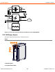

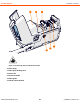


X8 MIG WELDER 2.2 System structure
3. USB connector
Connect a USB memory stick to upload the welding procedures (WPS) or Wise features to the power
source or update firmware if a wireless connection is unavailable.
4. Control Pad connector
Connect Control Pad to the power source with a cable to charge its battery or to use it in wired mode.
5. Front panel
6. Front panel latch
Pull to open the front panel and reveal the coolant container.
7. Coolant circulation button
Press to pump the coolant through the system.
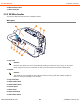
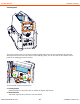
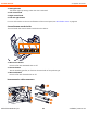
Rear
6
2
3
3
2
4
4
8
5
5
9
7
10
1
11
12
1. Transportation handle
2. Welding current cable connectors (positive pole)
3. Earth return cable connectors (negative pole)
4. Measurement cable connectors
Connectors for wire feeder 1 on the left, wire feeder 2 on the right side of the power source.
5. Control cable connectors
Connectors for wire feeder 1 on the left, wire feeder 2 on the right side of the power source.
6. Ethernet connector
7. Power switch
8. Coolant outlet hose connector
9. Coolant inlet hose connector
10. Rear panel
11. Mains cable
OPERATING MANUAL | EN 12
©
KEMPPI | 2018-09-28