
User guide

KENCO ENGINEERING COMPANY
P.O. BOX 470426, TULSA, OK 74147-0426 ♦ PHONE: (918) 663-4406 FAX: (918) 663-4480
http://www.kenco-eng.com e-mail: info@kenco-eng.com
K99M INSTALLATION / OPERATING INSTRUCTIONS
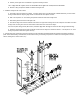
Installation Instructions-(See Exploded Drawing On Page 2 For Parts Listing)
Only Qualified Personnel Who Are Familiar With Gauge Glass Valves And Their Operation Should Undertake Installation Of This Product. Failure To
Properly Install Could Result In Serious Personal Injury And Property Damage.
Note: For Steam-Water Applications, Use Needle Nose Pliers To Remove Retainer Springs (Item 22) And Discard Ball Checks (Item 21) On
Both Top And Bottom Valve Assemblies.
1. Prior To Actual Installation, Turn Handwheel On Upper And Lower Valve On Gauge Clockwise Until Stem Closes Against Seat.
2. Remove Union Nut and Process Connection From Top & Bottom Valve Assembly (Items 24 & 25). Mount Upper And Lower Process Connections
To Vessel, Using Teflon Tape On All Pipe Thread Connections. Make Sure That The Face Of The Process Connections Are Aligned Vertically With
Each Other.
3. Inspect O-Ring Seal (Item 23) On Face Of Upper & Lower Valve Body To Make Sure It Is In Groove And Installed With Lubricant. Kenco Factory
Installs O-Rings Using A Silicone Based Seal Lubricant.
4. Thread Union Nuts Onto Gauge Valve Bodies And Center Lower And Upper Gauge Valve Body And Union Nuts With Installed Gauge Process
Connections Before Tightening Union Nuts Back In Place. Tighten Union Nuts Until They Bottom Out On Valve Assembly.
5. Re-Check Vessel Connections As Well As 1/4” And 1/2” FNPT Vent/Drain Connections On Each End Of Gauge To Ensure That They Are Pressure
Tight.
6. Turn Valve Handwheels Counterclockwise Very Slowly To Avoid Excessive Thermal Shock And Mechanical Stress On Tubular Gauge Glass Sight
Tube Contained Inside Gauge Frame.
7. Allow Gauge Temperature And Pressure To Slowly Equalize With Vessel.
Note: Failure To Slowly Bring Gauge Into Service Will Cause Rapid Pressurization Of Sight Tube Which Could Result In Serious Personal
Injury And Property Damage.
8. Inspect Gauge To Insure That There Are No Leaks Prior To Proceeding With Installation.
9. Open Valves Completely After Temperature And Pressure Have Equalized To Permit Ball Checks In Valve Bodies To Properly Seat In The Event Of
Possible Glass Breakage. (Note: In Some Circumstances Where Liquid Being Gauged Tends To Surge In A Rapid Manner, Ball Checks Can Seat And
Give A False Level Reading).
Maintenance Instructions
1. During System Shutdown, Gauge Valves Are To Be Left Open To Allow Gauge To Lose Pressure And Cool To Ambient Temperature With Vessel.
2. Should Gauge Need Maintenance While Vessel Is Still In Service, Valves On Each End Of Gauge Are To Be Closed Completely To Allow Gauge To
Cool To Ambient Temperature If Necessary. Liquid Can Then Be Carefully Drained By Using 1/4” Or 1/2” Npt Connection Port On Lower End Of
Gauge.
Note: Do Not Proceed With Any Maintenance Unless Gauge Has Been Relieved Of All Pressure Or Vacuum And Has Been Allowed To Reach
Ambient Temperature. Gauge Should Also Be Flushed Out To Remove Any Hazardous Liquids Before Handling If Possible.
3. Cleaning Inside Of Sight Tube Can Be Done Without Removal Of Tube Itself. This Can Be Accomplished By Using A Tube Brush With
Access Through 1/2” Fnpt Vent/Drain Connection Ports On Each End Of Gauge.
4. Removal Of Sight Tube Contained Inside Gauge Frame Is As Follows:
A. Remove Existing Clear Polycarbonate Or Expanded Metal Shield By Bending Crimped Portion Of Gauge Frame On Each End
Away From Shield So It Can Easily Slide Out.
B. Remove (2) Hex Socket Head Cap Screws In Blocks On Each End Of Gauge Holding 1-3/8” Square X 1/4” Thick O-Ring
Compression Plates In Place.
C. Push Sight Tube Up Into Upper Block As Far As Is Required To Enable Lower End Of Sight Tube To Swing Out From Frame
Inside Gauge Frame.
Note: On Very Short Gauges, It May Be Necessary To Remove Sight Tube Through 1/2” Fnpt Vent Port On Upper End Of Gauge.