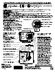
KENCO ENGINEERING COMPANY P.O. BOX 470426 ● TULSA, OK 74147-0426 PHONE: (918) 663-4406 ● FAX: (918) 663-4480 www.kenco-eng.com ● e-mail: info@kenco-eng.com INSTALLATION INSTRUCTIONS FOR MODEL KLC OIL LEVEL CONTROLLERS WITH ADAPTERS (INCLUDING HIGH PRESSURE MODELS) Note: For fire safe oil level controllers, see additional instructions in this work sheet covering installation of fire safe valves. I.
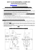
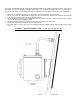
FIGURE 2: MECHANICAL LUBRICATOR –11 AND –11-FS OPTION Drill holes in the lubricator housing as shown and mount the controller with the inlet located on the top side using the seal washers and mounting bolts provided. Place the seal washers between the controller and the lubricator housing. OIL LEVEL CONTROLLER WITH –14 AND –14 –FS OPTION (Cooper Superior)-Formerly White Remove the triangular blind flange located on the compressor and mount the controller assembly in its place.
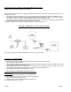
OIL LEVEL CONTROLLER WITH –17 (Waukesha VHP Engines F2895, F3251, F5108, L5790 & L7042), -18 (-17 with 1618 Low Flow Meter), -27 (for newer 2-bolt door Waukesha engines same as –17), –37 (Waukesha P9390), -38 (same as –37 with 1618 Low Flow Meter), -39 (same as -37 with 14308 Low Flow Meter), -40 (same as -17 with 14308 Low Flow Meter), and –FS OPTIONS Remove the cast aluminum inspection door from the engine. Remove the clamp bar from the old door.
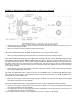
III. INSTALLATION INSTRUCTIONS FOR FIRE SAFE VALVES: MODEL 50-KFS AND 75-KFS (PATENT NO. 3,877,476) NOTE: All lines between thermal valves, supply tanks and the controller must be made of steel. DO NOT use rubber hose. The lines should be 3/4” I.D. The eutectic fuse element should always be in a downward position to help the element melt when heat is applied to the valve. The 50-KFS valve has 1/2” FNPT threads and should be installed in the oil supply line as close to the controller as possible.