Use & Care Guide Model No. 153.592500 50 Gallon Tall 153.592600 66 Gallon Tall 153.592800 80 Gallon Tall Kenmore Elite Hybrid Electric Heat Pump Water Heater ® For potable water heating only. Not suitable for space heating. INSTALLER: Affix these instructions to or near the water heater. OWNER: Retain these instructions for future reference. ADVERTENCIA Si no puede leer o entender el inglés y necesita el manual de instrucciones en español, puede solicitarlo al 1-800-821-2017.
TABLE OF CONTENTS Product Warranty .......................................................................................................................................3 Typical Installa on ......................................................................................................................................4 Important Safety Informa on..................................................................................................................5-7 Ge ng Started .........................
PRODUCT WARRANTY KENMORE ELITE LIMITED WARRANTY WITH PROOF OF SALE, the following warranty coverage applies when this water heater is correctly connected, installed, operated and maintained according to all supplied instructions. In all cases, replacement units, tanks or parts are warranted only for the unexpired portion of the warranty period from the original date of sale. 4.
COMPLETED INSTALLATION TYPICAL TYPICAL INSTALLATION FOR 208V/240V Air Filter Condensate Drain Access Cover Connectivity Port User Interface Module (UIM) xxxx x xxxx x xxxx x xxxx x Temperature and Pressure Relief Valve Union* Upper Element and ECO Shut-off Valve (Hot) Hot (Outlet) Primary Condensate Drain (3/4” PVC) Discharge Pipe (Do Not Cap or Plug) Thermal Expansion Tank Lower Element Cold (Inlet) Drain Valve Union* Drain Pan Drain Line Drain Shut-off Valve (Cold) *NOTE: If copper piping is
Read and follow all safety messages and instruc ons in this manual. This is the safety alert symbol. It is used to alert you to poten al physical injury hazards. Obey all safety messages that follow this symbol to avoid possible property damage, serious injury or death. Do not remove any permanent instruc ons, labels, or the data plate from either the outside of the water heater or on the inside of the access panels. Keep this manual near the water heater.
SAFETY IMPORTANT SAFETY INFORMATION T o reduce the risk of property damage, serious injury or death, read and follow the precau ons below, all labels on the water heater, and the safety messages and instruc ons throughout this manual.
According to a na onal standard American Society of Sanitary Engineering (ASSE 1070) and most local plumbing codes, the water heater’s thermostat should not be used as the sole means to regulate water temperature and avoid scalds. Properly adjusted Thermosta c Mixing Valves, installed at each point of use, allow you to set the tank temperature to a higher se ng without increasing risk of scalds.
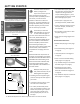
GETTING STARTED Review all of the instruc ons before you begin work. If you aren’t sure that you can safely and properly do this work yourself, contact a qualified person of your choice, such as a licensed plumber or electrician to have the work done. Improper installa on can damage the water heater, your home and other property, and can present risks of serious injury or death. 1 GETTING STARTED Figure 1 - Flexible connectors use compression fittings and do not require soldering.
INSTALLATION ✓ Step 1: ✓ Verify that your home is equipped and up-to-date for proper opera on Installing a new water heater is the perfect me to examine your home’s plumbing system and make sure the system is up to current code standards. There have likely been plumbing code changes since the old water heater was installed. We recommend installing the following accessories and any other needed changes to bring your home up to the latest code requirements. Use this checklist and inspect your home.
INSTALLATION INSTALLATION BACKGROUND: Water expands when heated, and the increased volume of water must have a place to go, or thermal expansion will cause large increases in water pressure (despite the use of a Pressure Reducing Valve on the home’s main water supply line). The Safe Drinking Water Act of 1974 requires the use of backflow preventers and check valves to restrict water from your home reentering the public water system.
INSTALLATION 3 The floor can support the weight of a full water heater. Table 1 Capacity Filled Weight (lbs) 50 Gallon 573 66 Gallon 796 80 Gallon 921 Your area is not prone to earthquakes. If it is, use special straps as required by local building codes. 4 NOTICE! The state of California requires bracing, anchoring, or strapping the water heater to avoid its moving during an earthquake. Contact local u li es for code requirements in your area, visit h p://www.dsa.dgs.ca.
INSTALLATION Step 3: Removing the old water heater Read each installa on step and decide if you have the necessary skills to install the water heater. Only proceed if you can safely perform the work. If you are not comfortable, have a qualified person perform the installa on. Locate the water heater’s circuit breaker and turn it OFF (or remove the circuit’s disconnects). 1 INSTALLATION 2 On the old water heater, remove the electrical junction box access panel.
INSTALLATION Installing the new water heater Completely read all instrucons before beginning. If you are not sure you can complete the installa on, DO NOT RETURN THIS UNIT TO THE STORE. Schedule an appointment with a qualified person to install your water heater. 1 2 3 Install a suitable drain pan that is piped to an adequate drain. Set the water heater in place taking care not to damage the drain pan. NOTICE! Most codes require se ng the water heater in a suitable drain pan piped to an adequate drain.
INSTALLATION Condensate Drain Access Cover Primary Drain Connection Secondary Drain Connection Overflow Slot Condensate Pump Wiring Loop (Loop Located Close to the Drain Connections) Figure 15 - Condensate Pump Wiring INSTALLATION Step 6: Install Condensate Drain Lines: NOTE: When making condensa on connec ons to the primary connecon DO NOT over ghten! These connec ons should be HAND TIGHTENED ONLY. Over ghtening could crack or damage the condensate drain pan.
INSTALLATION valves that are compa ble with potable water. Use only full-flow ball or gate valves. Other types of valves may cause excessive restric on to the water flow. a Thermosta c Mixing 2 Install Valve at each point of use (for example, kitchen sink, bathroom sink, bath,shower). Consult the valve manufacturer’s instruc ons or a qualified person. DISCHARGE PIPE DRAIN PIPE WARNING! Hot water provided by solar hea ng systems can cause severe burns instantly resul ng in severe injury or death (page 6).
INSTALLATION IF YOU HAVE COPPER PIPES: INSTALLATION If your home has copper water pipes, you can solder the water pipe connecons or use compression fi ngs which don’t require soldering. Compression fi ngs are easier to install than soldering pipe. Check with local plumbing officials to determine what types of pipe materials are suitable for your loca on. Do not use lead-based solder.
INSTALLATION Open a hot water faucet and allow the water to run un l it flows with a full stream. 4 Let the water run full stream for three full minutes. 5 Close the hot water faucet and replace the aerator. Check inlet and outlet connecons and water pipes for leaks. Dry all pipes so that any drips or leaks will be apparent. Repair any leaks. Almost all leaks occur at connecons and are not a tank leak. 6 This water heater requires a 240/208 VAC single phase 30 amp power supply, at 60Hz.
INSTALLATION Operation The water heater is now ready for normal operation. To keep your water heater working safely and efficiently and extend its life, perform maintenance as described in maintenance section beginning on page 29. Start-up and Opera on INSTALLATION NOTE: The default opera ng mode is Hybrid, to select a different mode see Opera ng Modes sec on on page 19. PRIOR TO BEGINNING OPERATION: Air filter is factory installed with tabs oriented down for shipping.
INSTALLATION Understand how to use the User Interface Module to set the various modes and func ons. 1 Hybrid Mode is the recommended Opera ng Mode. Understand the various Opera ng Modes and which mode may be best, based on ambient temperature and hot water demands. 2 Understand the importance of rou ne inspec on/ maintenance of the condensate drain pan and lines. This is to prevent any possible drain line blockage resul ng in the condensate drain pan overflowing.
INSTALLATION INSTALLATION Vacation Mode The controller will maintain a 60°F tank temperature while in Vacation setting. This mode is recommended when the water heater is not in use for a long period of time, to minimize energy consumption and prevent the water heater from freezing during cold conditions. To enter Vacation Mode Press and hold the up ↑ button.
INSTALLATION Temperature Unit Indication Light Temperature Up (Increase) Button °F °C Display Segment DAYS Temperature Down (Decrease) Button Vacation Time Indication Figure 26: User Interface Module (UIM) Massachusetts: Install a vacuum relief in cold water line per section 19 MGL 142.
DIAGNOSTIC CODES WARNING! Electric Shock Hazard; Disconnect power before servicing. Do not remove the plac c guard from over wiring. Do not touch electrical wiring. Failure to do so can result in death or electrical shock. DISPLAY SHOWS * * INDICATES CORRECTIVE ACTION - -- --- (series of dashes) Unit is doing a system diagnostic. ICE Heat pump is in defrosting cycle. HPO Ambient temperature <45°F or >120°F, average tank temperature of 59°F or less.
DIAGNOSTIC CODES WARNING! Electric Shock Hazard; Disconnect power before servicing. Do not remove the plac c guard from over wiring. Do not touch electrical wiring. Failure to do so can result in death or electrical shock. * EoF Condensate management 1. 2. 3. 4. 5. 6. 7. * * Ensure unit is installed level. Check for blocked primary or secondary condensate drain lines, clear drain lines as necessary.
TROUBLESHOOTING CHART PROBLEM POSSIBLE CAUSE(S) NO DISPLAY 1. Sleep Mode 1. Touch any button to wake up UIM NO HOT WATER 1. 1. 2. No power to the water heater (No lights on the unit are on). Unit in Vacation mode 3. ECO tripped 3. 4. Hot water usage pattern exceeds the capability of the water heater in current mode Non-functioning upper temperature sensor Faulty thermostatic mixing valve. Leak in plumbing system 4. Check for tripped breaker or disconnect. Restore power to unit.
TROUBLESHOOTING WARNING! Working near an energized circuit can result in severe injury or death from electrical shock. • Locate the electrical junction box on the side of the water heater and remove the cover. WARNING! When you are finished, be sure all covers are secured to reduce the risk of fire and electric shock. • Identify the two power wires. The power wires are usually black/black or black/red-the green or copper wire is the ground wire.
TROUBLESHOOTING Check/Reset Energy Cut Off ECO Bu on. 5 1 • Replace the insulation and the upper access panel. 2 Reset Button • Turn the power back on to the water heater. WARNING! Be sure all covers are secured to reduce the risk of fire and electric shock. Drips from T&P Relief Valve Discharge Pipe TROUBLESHOOTING FIgure 30 - Energy Cut Off (ECO) bu on The Energy Cut Off (ECO) shuts off power to the water heater’s elements if the temperature of the water in the tank gets too hot.
TROUBLESHOOTING Water Heater Sounds During the normal operation of the water heater, sounds or noises may be heard. These noises are common and may result from the following: • Normal expansion and contraction of metal parts during periods of heat-up and cool-down. • Sediment buildup on or around the elements could create varying amounts of noise and may cause premature tank failure. Drain and flush the tank as directed under the “Draining and Flushing” section.
TROUBLESHOOTING User Interface Module (UIM) set too low. If the water temperature at several faucets is too cool, adjust the UIM according to the instruc ons in Step 12 of the Installa on sec on of this manual. Undersized water heater. If your water heater runs out of hot water too quickly, it may be too small for your needs. If the water heater is old, consider replacing it with a larger model.
MAINTENANCE Rou ne maintenance will help your water heater last longer and work better. If you cant perform these rou ne maintenance tasks yourself, call the Sears Parts & Repair Service Center at 1-800-488-1222 for further assistance. Water Heater Maintenance A er the first six months, drain and flush the water heater and inspect the anode rod. Depending on the hardness of your water, repeat this process at least annually, or more frequently if needed.
MAINTENANCE Anode Rod. The anode rod is a sacrificial metal rod that helps reduce corrosion and premature failure (leaks) in the tank. The anode rod is a consumable item. Inspect the anode rod a er the first six months of opera on when you drain and flush the tank. Replace the anode rod if it is substan ally worn out or depleted. Therea er, inspect the anode rod annually or more frequently if needed. If you use a water so ener, your anode rod will deplete faster than normal.
MAINTENANCE Open a hot water faucet and let the hot water run un l it is cool. Make sure the new element is the correct replacement by referring to the water heater’s data plate for voltage and wa age informa on. 8 Clean the threads in the tank opening with a rag. Insert the new element equipped with a rubber gasket. NOTE: Use a drop of hand dishwashing liquid to lubricate the gasket to help avoid damaging the gasket as it is being ghtened. Tighten with an element wrench.
MAINTENANCE • A replacement ECO (available by calling the number in the repair parts list located on page 34). A business card to check the gap between the ECO and tank. • Tape and a permanent marker to mark the wires • A flat blade and a Phillips screwdriver Steps for Replacing the ECO: 1 Turn the power OFF at the circuit breaker or remove disconnects. NOTICE: It is not necessary to drain the tank to replace an ECO. Open the electrical junc on box the side of the water heater.
MAINTENANCE • Note that a dripping T&P Relief Valve is usually caused by the home’s water pressure being too high or the lack of a Thermal Expansion Tank. If your T&P Relief Valve drips refer to “Drips from T&P Relief Valve Discharge Pipe” section on page 26. Air Filter Maintenance The heater will monitor the heat pump opera on status and indicate whether the filter should be cleaned.
REPAIR PARTS ILLUSTRATION ITEM 6 22 21 PARTS DESCRIPTION 12 1 Personnel Protector 9003900005 2 Element (4500 Wa s) 9000092015 3 Energy Cut-Off (ECO) Switch 9008167015 4 Temperature & Pressure Relief Valve (T&P) 9000728015 5 J-Tube (at hot water outlet) 11.25” for 50 gallon 9008848005 5 J-Tube (at hot water outlet) 14.