E L I T E ® ilator Use & Care / installation Manual VE Or Manual de uso y cuidado /instalaci6n Models Modelos 233.59960400 233.59966400 o u O 99043579B Sears, Roebuck and Co., Hoffman Estates, UL60179 U.S.A. www.sears.
SECTION ..................................................................... PAGE Warranty .............................................................................. 2 Safety Instructions ............................................................... 2 Operation ............................................................................. 3 Cleaning, Servicing ............................................................ 3 Parts Included With Downdraft ...........................................
Always turnthedowndraft blower onbefore youbegincookingtoestabIish anairflowinthekitchen. LetthebIower runfor a fewminutes tocleantheairafteryouturnthecooktop off. Thiswillkeepthewholekitchen cleaner andbrighter. CONTROLS WARNING: Always disconnect supply before cleaning unit. electric power Use a mild detergent suitable for painted surfaces. DO NOT USE ABRASWE CLOTH, STEEL WOOL PADS, OR SCOURING POWDERS. Vacuum blower to clean. Do not immerse blower in water.
Aluminum Grease Filters (Qty. 2) J J Screwdriver (Fmat& Phillips) Drill Parts Bag (Contains leveling brackets & mounting hardware.
Kenmore downdrafts aredesigned toperform efficiently whenattached toIongrunsofduct=Asa pointofreference, thishood wiIIfunction atapproximately 80%ofitsratedairflowwhen200equivalent feetof7"roundductwork isattached= Usethischart tocalculate theequivalent ductlengthofyoursystem= Broan Model 428 3¼-in, × 10-in, Right-angme Embow Equivalent length _ 64n= Round Wall Cap Equivalent Sears Modemlength 59691 34 ft. 8.5 ft. BroanModem 401 StraightDuct (6-fL w/o damper) 3¼qn. x lOqn.
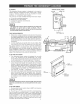
PLANNtNG This downdraft blower system exhaust airborne contaminants of gas or electric cooktops. It peninsula, or conventional walI TYPICAL _NSTA_ON is designed to be used to when cooking with a variety can be mounted in island, locations. This unit can be easily installed following these basic steps: ® Cut out the countertop opening. ® Mount the unit in the cabinet. ® Connect the ductwork and electrical. o Install the cooktop.
CHANGING BLOWER DISCHARGE (Optiona0 Theblower is shipped withitsdischarge facingDOWN. FoF lowthesestepsONLY if: o theposition oftheblower discharge needs tobemoved soductwork doesnotinterfere withfloorjoists,plumbingorwiringbelow. ® itis necessary torotatetheblower discharge tothe RIGHT orLEFT. Placetheunitonitsbackona tableorworksurface. BLOWER NUTS CLAMP DOWN DISCHARGE o MOVING BLOWER LEFT OR R_GHT 1. Loosen the 4 nuts and 2 clamp channels. 2. Slide blower to desired position. 3.
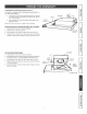
CUT COUNTERTOP OPENING 1. Lay out and cut the cooktop cut-out far enough FORWARD so downdraft will fit behind it. 2. Set cooktop in place and slide it as far forward as possible. Center and square it with edges of countertop. 3. Place the plastic template against the back flange of the cooktop and center it. Trace around template to mark the downdraft opening. 4. Remove cooktop from countertop. 5. Cut downdraft opening. Be careful not to chip edges of countertop. MOUNT THE UNiT 1.
_NSTALL ELECTRICAL W_RING WIRING D_AGRAM 1. The Downdraft Blower system draws 4 AMPS and requires a 120 VAC, 60 Hz circuit. 2. The unit has a 18 in. Iong power cord with a 3-pronged plug. Plan to provide a grounded outlet in a location which will allow the unit's power cord to reach. UNE tMPORTANT - LOCATION OF ELECTRICAL OUTLET: If Model 59960 is being installed in a 30" wide cabineL_ or- If Model 59966 is being installed in a 36" wide cabinet._ ...
WhentousetheRemoteUP/DOWN ControJ TheRemote UP/DOWN Controlshould be used when your cooktop has a burner that is within 4 inches of the UP/DOWN Button on the downdraft chimney. The Remote UP/DOWN Control can be used for convenient UP/DOWN operation of the downdraft chimney (even when a burner is more than 4 inches from the UP/DOWN Button of the downdraft chimney). How to use the Remote UP/DOWN 2.000 --f- .250 DIA. HOLES .
Congratulations on making a smart purchase. Your new Kenmore ® product is designed and manufactured for years of dependable operation. But like all products, it may require preventive maintenance or repair from time to time= That's when having a Master Protection Agreement can save you money and aggravation.
SECCION ................................................................ PAGINA Garant_a .............................................................................. 12 Instrucciones de seguridad .................................................. Operaci6n ........................................................................... Limpieza y servicio ............................................................ Piezas induidas con el ventilador de tire descendente ..........................................
Siempre encienda eIventilador detirodescendente antesde comenzar a cocinar, paraestablecer unfiujodeaireenIa cocina. Despues deapagarlaestufadejequeeIventilador funcioneunosminutosma.sparaIimpiarel aire. Esto mantendra todalacocinamaslimpiay brillante. CONTROLES ADVERTENCIA: Siempre desconecte el suministro de energ_a etectrica antes de timpiar Ja unidad. Utilice un detergente suave adecuado para superficies pintadas. NO UTHUCE TELAABRASWA, HBRA METAUCA O POLVOS DESENGRASANTES.
BoJsa conpiezas (Contiene Iasescuadras deniveiaci6n y losaccesorios parael montaje) FHtros dealuminioparagrasa (Cantidad: 2) J J DestornHBador (chato y Phillips} Pedoradora Q Cinta m_trica L_piz Sierra de punta "°" Serrucho de punta 14 Cinta adhesiva para conductos S Ajustador de tuercas de 1/4" PeRador de cable
Los ventiladores de tire descendente Kenmore fueron disehados para que funcionen de manera eficiente al conectarse a largos recorridos de conducto. Como punto de referencia, esta campana funcionara a aproximadamente el 80% de su fluio de aire nominal cuando se conecte a 61 m (200 pies) equivalentes de conducto redondo de 17.8 cm (7 pulg.). Utilice este cuadro para calcular el largo eqovalente de conducto de su sistema. Sears Broan Modelo 428 Acodado de 90 ° de 3¼ pulg. x 10 pulg. Largo equivalente 2.
PLANEACI6N Eldiseflo deestesistema ventilador detirodescendente permite que seutilice paraevacuar loscontaminantes transportados pore!aire cuando cocina conunavariedad decubiertas deestufa e!_ctricas o degas.Elmontaie puede serdetipoisia,peninsula oenunapared tNSTALAC!6N CUBIERTA ® ® o o Corte una abertura Monte la unidad en Conecte los ductos Instale la superficie siguiendo SUPERFICIE DE LA ESI'UEA convenciona].
_b CAMBIO DE LA DESCARGA DEL VENTILADOR (Opcional) El ventilador sale de f&brica con Ia descarga orientada hacia abajo. Siga estos pasos SOLAMENTE en e! case de que: o se necesite cambiar la posici6n de la descarga del ventilador, de mode que el sistema de ductos no interfiera con las vigas deI piso o con las canalizaciones electrica o de plomer[a que estan debajo. ® sea necesario girar la descarga del ventilador hacia Ia DERECHA o la IZQUERDA.
CORTE LA ABERTURA EN LA CUB[ERTA 1_ Distribuya y haga el corte en [a superficie de la estufa Io suficientemente a[ejado HACHA EL FRENTE, de modo que el ventilador de tiro descendente quede detr_s del mismo. 2. Ponga la superficie de Ia estufa en su Iugar y desifcela Io m_s que pueda hacia et frente. Centrela y p6ngala a escuadra con los bordes de la cubierta. 3. Ponga Ia pIantilla de plastico contra la pestafia posterior de la superficie de Ia estufa y centrela.
INSTALE EL CABLEADO ELI_CTRJCO DIAGRAMA DE CONEXtON ELC:CTRICA 1. Ei sistema de ventiiaci6n de tiro descendente interior consume 4 amperios y requiere an circaito de 120 VCAy 60 Hz. 2. La unidad tiene un cable de alimentaci6n de 45 cm (18") con una clavija de tres patas. Planee colocar un tomacorriente con conexi6n a tierra en an iugar que el cable de alimentaci6n de la unidad pueda aicanzar. IMPORTANTE: ELC:CTRICO: UBICACION Y_L WNT "- iLK INTERRUPTOR NC B_.
AJUSTE E! ventilador de tire descendente se ajusta en la f_brica para un funcionamiento adecuado= Sin embargo, et transporte y el manejo podrian afectar la posici6n de! interrupter de activaci6n= Para ajustar la posici6n de1 interrupter de activaci6n: 1. En case de que la campana est_ conectada a la toma de corriente electrica, desconectela. 2.
lnstalaciSn 1. Usando la plantilla que aparece a la derecha, trace el patr6n de tres orificios en la cubierta. Marque el centre de los tres orificios qu@ se van CAJA DE CABLEADO a Racer. 2. Con un taladro, perfore cuidadosamente los tres orificios en la superficie de la cubierta. Tenga cuidado de no da[iar ni astillar la superficie de la cubierta cuando perfore los orificios. 3. Saque e! control de la bolsa de plastico.
¼ Ctave 30N n.
...... ,,,, ,,i, Your Home 'ii'ii'ii'ii'ii'ii'ii'ii'ii'ii'ii'ii'ii'ii'ii'ii'ii'iill For repair-in your home-of all major brand appliances, lawn and garden equipment, or heating and cooling systems, no matter who made it, no matter who sold it! For the replacement parts, accessories and owner's manuals that you need to do-it-yourself. For Sears professional installation of home appliances and items like garage door openers and water heaters. (1-800-469-4663) Call anytime, day or night (U.S.A. www.sears.