Installation ndercounter Instructions _hwasher (Stainless Steel GiantTub Models) Instrucciones de Instalacion Lavavajillas ernpotrado (Modelos con tina gigante de acero ino×idable) instructions d'installation Lave-vaisselle encastre (Modeles a cuve geante en acier ino×ydable) Table of Contents ............................................................................. indice .............................................................................................. 2 17 Table des matieres ....
Table of Contents installation Dishwasher Safety Installation Requirements Tools and Location ................................. parts Requirements Drain Requirements Water Supply Electrical 3 ................................. 3 ............................. Requirements Requirements Prepare cabinet opening where there are no existing 3 .......................... 5 ...................... 5 .......................... .............................
insta//ation Requirements Make sure all these parts are included. 1-800-4MY-HOME. Tools and Parts Gather the installation. required tools and parts before See separate dishwasher.
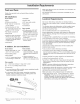
Product dimensions 3/4" (1.9 cm) insulation may be compressed (not used on all models) ,,_:-_24-1/2" Cutout dimensions (62.2 cm)*_ All surfaces must be free from intrusions 7-1/2" 34" 7-1/2" (86.4 cm) rnin. _ _(-_ 21" (53.3 ore) _D, t r(15.2 cm) SIDE VIEW (5.1 cm) (7 cm) 23-7/8" (60.6 cm) 3-1/4" (8.9 cm) (8.3 cm) Cut holes in shaded area of cabinet water line- drain line- direct wire power 10" walls or floor as specified (7 cm) below: 1/2" (1.3 cm) 1-1/2" (3.
Drain Requirements Electrical . Use the new drain hose supplied with your dishwasher. If this is not long enough, use a new drain hose with a maximum length of 12 feet (3.7 m) that meets all current AHAM/IAPMO test standards, is resistant to heat and detergent, and fits the 1" (2.5 cm) drain connector of the dishwasher. o Connect drain hose to waste tee or disposer inlet above drain trap in house plumbing and 20" (50.8 cm) minimum above the floor.
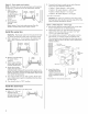
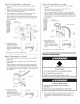
Installation Instructions install the drain hose IMPORTANT: Always use a new drain hose installing a new replacement dishwasher. 1. Electrical Disconnect breaker Failure electrical box before power installing to do so can result Shock Drill box or circuit in death or electrical 2. Turn Prepare existing supply.
Option 2, No waste disposer Option Cut end of drain section). 2. Attach drain hose to air gap with large spring-type clamp. If the drain hose was cut, use a 1-1/2" to 2" (3.8 to 5 cm) screw-type clamp s. Use a rubber type clamps* if needed air gap: 1. 3. hose - with (do not cut ribbed No waste 1. Cut end section). 2. Attach of drain drain (3.8 to 5 cm) disposer hose hose - no air gap: if needed to waste screw-type (do not cut ribbed tee with clamp 1-1/2" to 2" *.
Option2, Powersupplycord 2. method: Connect drain hose to waste tee or waste disposer using one of the following methods: NOTE: A mating, three prong, ground-type wall receptacle is required in a cabinet next to the dishwasher opening. , Option 1, Waste disposer- 1. , Option 2, No waste disposer- , Option 3, Waste disposer- Drill a 1-1/2" (3.8 cm) hole in the cabinet rear side. Preferred and optional locations are shown.
Option2, Nowastedisposer- withairgap: 1. Cutend of drain hose if needed (do not cut Option ribbed Attach drain hose to air gap with large spring-type clamp. If the drain hose was cut, use a 1-1/2" to 2" (3.8 to 5 cm) screw-type clamp s. 3. Use a rubber type clamps* Cut end section). 2. Attach j_ disposer of drain drain (3.8 to 5 cm) hose hose - no air gap: if needed to waste screw-type (do not cut ribbed tee with clamp 1-1/2" to 2" s.
Remove two screws panel to dishwasher or Phillips attaching access panel and lower using a 1/4" hex socket, nut driver Turn both height. screwdriver. 3. Remove surface. panels and set panels 4. Check that grounding panel. aside on a protective front leveler legs to the same If the minimum cutout height is less than 34" (86.4 cm), the rear wheels can be removed for additional clearance.
Install the door handle {some Kenmore IMPORTANT." procedure. Do not scratch the front panel models) Elite during this Remove the door handle and hardware bag containing the setscrews and Allen wrench from the cardboard box. 2. Start 3. Place handle on mounting appear as a "smile" when facing down. in handle. Push the door handle short end of the Allen Tighten wrench studs.The installed, handle should with the set screws 1/4 turn past snug. Instructions.
Check door spring tension Level the dishwasher 1. With another person holding the dishwasher to prevent it from tipping, open and close the door a few times. If the door closes or falls open under its own weight, the door tension will need to be adjusted. 2. To adjust from the 3. With from 4. The screw can be put into one of three holes Ill, 1_41, B in front leg of dishwasher. If the door closes by itself, move the tensioner to a higher number hole and replace screw.
Form bare ground wire into ground wire hook clockwise and under the washer. Make Electrical Connection Check "Electrical You need to: requirements" o have the correct electrical grounding method. section. 5. Securely tighten ground a U-shaped hook. Wrap around ground connector connector. supply and recommended ground wire washer ground connector ./ If you are: o direct wiring, use Option + using a power supply Option 1 cord, use Option 2 1, Direct wire method ground 1.
Connect Helpful to water Secure onto copper tubing about c. Put the tubing as far as it will the into the elbow nut and ferrule onto the elbow and positioning easily. forward position and threads. Be gentle the copper tubing, start ferrule go. the nut when handling it bends and kinks Tip Over Do not ferrule elbow_ _1 vibration supply line base, frame so that it does or motor. during operation, route not touch the the water down until on open completely door.
Bottom sound pad installation 1. Remove the bottom sound dishwasher and take it out 2. Place pad on the floor in front making sure lettering is facing down. (on some models) pad from inside the of the plastic bag. of the dishwasher, up and vinyl pad 3. Hold the two panels dishwasher leg. 4. Reinstall the screws panel and the slots screw first. together and place through the holes in the lower panel.
Check operation 1= Read the Use and Care Guide that came with your dishwasher. 2. Check that all parts have been installed and no steps were skipped. 3. Check that you have all the tools you used. 4. Start dishwasher and allow it to complete the shortest wash cycle. After the first two minutes, unlatch door, wait five seconds, then open door. Check to see that there is water in the bottom of the dishwasher tub. Check that dishwasher is working properly.
indite Instrucciones de instalaci6n Seguridad de la lavavajillas Requisitos de instalaci6n Herramientas ......................... 17 .......................... y piezas de ubicacion Requisitos de desag_e Requisitos del suministro Requisitos electricos 18 ......................... Prepare la abertura del gabinete usando las conexiones de servicio existentes .............. 21 Prepare la abertura del gabinete donde no existen conexiones de servicio ................
Requisitos de instalacion Herramientas AsegSrese de que todas las piezas estan, Ilarne al 1-800-4MY-HOME. y piezas Retina las herramientas cornenzar la instalaci6n. y piezas necesarias esten inchidas. Si no Io Vea la lista de piezas que viene por separado para ver accesorios estan disponibles para su lavavajillas.
Dirnensiones El aislamiento de 3/4" (1,9 cm) puede comprimirse (no se usa en todos los modelos) del producto ,,_---24-1/2" Dirnensiones de corte (62,2 cm) _ Todas las superficies deben estar libres de intrusiones "_"_-24" (61 cm) 7-1/2" 7-1/2" min.
Requisitos de desagiJe Requisitos ® Utilice la nueva manguera de desagL_e provista con su lavavajiilas. Si esto no fuera adecuado, use una manguera de desagQe nueva de una Iongitud maxima de 12 pies (3,7 m) que cumpla con todos los estandares de prueba vigentes de la AHAM/IAPMO, sea resistente al calory a los detergentes y quepa en el conector de desagQe de 1" (2,5 cm) de su lavavajillas.
instrucciones de insta/acion Conecte en "T" la manguera desperdicios o al recipiente de los siguientes metodos. Opci6n 1 : con de aire. recipiente Opcion 2: sin recipiente de aire. Peligro de Choque Desconecte el suministro fusibles o cortacircuitos o Opci6n 3: con de aire*. El_ctrico de energia en la caja antes de instalar choque esta 2. Cierre instrucci6n puede ocasionar la muerte o el_ctrico. 1.
Opci6n 2, Sin recipiente de desechos - con espaciador de aire: Opci6n 4. - Sin recipiente de aire: 1. Corte el extremo corte la seccion 1. de la manguera ranurada). si es necesario (no un conector * de hule o de tornillo para conectar al tubo de desperdicios.
Opci6n 2, Metodo del cable de suministro de energia: NOTA: Se necesita un contacto de pared con conexion a tierra de tres terminales en un gabinete que este al lado de la abertura de la lavavajillas. 1. Perfore un orificio de 1-1/2" o Opci6n de aire. ® Opcion 3, con de aire *. instalar la tuberia el orificio con un ojal de collar en el juego de cables de de agua de desechos - con de desechos- de agua.
Opci6n 2, Sin recipiente de desechos - con espaciador de aire: Opci6n 4, Sin recipiente de aire: 1. Corte el extremo corte la seccion 1. de la manguera ranurada). si es necesario 2. Sujete la manguera de desagLie conunaabrazaderagrandetipo de desagQe esta cortada, utilice tornillo de 1-1/2" o de 2" (3,8 a 5 3. Utilice un conector * de hule o de tornillo para conectar al tubo de desperdicios. (no al espaciador de aire resorte. Silamanguera una abrazadera × tipo cm).
2. Quite los dos torniiios que sujetan el panel de acceso y el panel inferior a la lavavajiiias, utilizando una llave de casquillo hexagonal de 1/4", una llave de tuercas o un destornillador Phillips. 3. Quite los paneles y col6quelos al lado en una superficie protectora. 4. Verifique que panel inferior. la pinza de puesta a tierra este sujeta al 8. Mida la altura de la abertura del gabinete desde la parte inferior del mostrador al piso en que se _ *_ instalara la lavavajillas (necesitara la ..
Instalaci6n de la manija (en los modelos IIVIPORTANTE: procedimiento. Kenmore No raye de la puerta Opcion 1, Fijacion mostrador Elite) el panel delantero durante este 1. Quite la manija de la puerta y la bolsa de herramientas que contiene los tornillos opresores y la Ilave Allen de la caja de carton. 2. Comience manija. a atornillar los tornillos opresores en la 3. Coloque la manija en los pernos de montaje.
6. Quite el carton de la base de la lavavajillas. Verifique la tension del resorte 1. Mientras otra persons sostiene la lavavajillas pars evitar que se incline, abra y cierre la puerta aigunas veces. Si la puerta se cierra o cae abierta por su propio peso, significa que la tensi6n de la puerta necesita ajuste. 2. Para ajustar la tensi6n del resorte de la puerta, desprenda el resorte de la pata posterior de la lavavajillas. 3. Con una Ilave quite el tornillo de tuercas o casquillo del tensor.
Opcion 1.- Metodo de cableado directo 1. Pase el cable directamente de manera que no toque motor de la lavavajillas ni la parte inferior de la tina la lavavajillas. el de 6. Apriete el conector de la abrazadera o los tornillos conector del conducto. 7, Reinstale terminales tornillos del la tapa de la caja de con los cables dentro de la caja de terminales. La tapa debe quedar del lado izquierdo. & AsegQrese 2.
1. Para evitar vibraci6n durante el funcionamiento, pase el tubo de suministro de agua de manera que no toque la base, el marco o el motor de la lavavajiiias. Asegure la lavavajillas del gabinete en la abertura 2. AI empujar el tubo de cobre hacia el empalme de compresion tanto como pueda, use una liave y apriete la tuerca del empalme de compresi6n en el tubo acoplador acodado en la vaivuia de entrada de agua. 3. Ponga papel absorbente bajo el tubo acoplador acodado.
Instalaci6n de la almohadilla acustica (enalgunos rnodelos) inferior 1. Quite la almohadilla inferior acOstica del interior de la lavavajillas y saquela de su bolsa de plastico. 3. Mantenga los dos paneles juntos y coloquelos contra la pata de la lavavajillas. 4. Vuelva a insertar los tornillos a traves de los orificios en el panel de acceso y las ranuras en el panel inferior. Inserte primero el tornillo del lado derecho. 2.
Verifique el funcionarniento 1. Lea el Manual lavavajillas. de Uso y Cuidado que 2. Verifique que todas las partes hayan que no se omitio ningQn paso. 3. Verifique si tiene todas vino con sido instaladas las herramientas que su y utilizo. 4. Ponga en marcha la lavavajillas y deje que complete el ciclo de lavado mas breve. Despues de que hayan transcurrido dos minutos, quite el seguro de la puerta, espere cinco segundos y abra la puerta. 5.
Table des matieres S@eurite instructions du lave-vaisselle E×igences Outillage d'installation .......................... et pieces 34 ............................. Emplacement d'installation Specifications la canalisation de d'evacuation Sp6cifications I'alimentation de en eau Specifications 61ectriques 34 ...................... ..................... ...........................
Exigences d'i'nstaflation Outillage et pieces Rassembler commencer tousles outils I'installation. Pour toutes Outillage V&rifier la presence pieces mentionnees 1-800-4MY-HOME.
Dimensions 1,9 cm (3/4") Le materiau isolant (pas utilis6 sur tous les modules) pourrait _tre comprime du produit 62,2 cm (24-1/2")* Dimensions de I'espace d'installation _ Toutes les surfaces _tre exemptes protuberances. de_ J 86,4 cm (34") min.
Sp6cifications d'evacuation de la canalisation Specifications Contacter un 61ectricien e Utiliser le tuyau d'6vacuation neuf fourni avec le lavevaisselie. Si ce tuyau n'est pas suffisamment long, utiliser un tuyau d'evacuation neuf de Iongueur maximaie 3,7 m (12 pi) qui satisfait les criteres de la normeAHAM/IAPMO en vigueur, r6sistant a la chaleur et aux detergents, et qui pourra _tre connecte sur le raccord de sortie de 2,5 cm (1") du lave-vaisselle.
instructions d'installation 1. Percer un trou de diametre 3,8 cm (1 1/2") dans la paroi du placard ou dans le plancher sur le c6te de I'espace d'installation le plus proche de I'evier. L Risque Interrompre de choc I'alimentation _lectrique _lectrique le lave=vaisselle (au niveau fusible ou disjoncteur) du tableau Le non=respect de cette instruction un d_c_s ou on choc _lectrique. 1. Interrompre 2.
Option2 - pas de broyeur 1. Si necessaire, couper (ne pas couper dans a dechets - avec brise-siphon I'extremit& du tuyau la section ondulee). : Option d'evacuation un raccord ou _ vis* siphon pour de caoutchouc* le raccordement et le raccordT avec entre du circuit bride brise- vaisselle. On recommande et de le fixer solidement travail.
Option2 - raccordernent parcordon d'alimentation : NOTE : La fiche du cordon d'alimentation devra &tre branchee sur une prise de courant _ 3 alveoles de configuration correspondante, reliee a la terre, installee dans autres emplacements emplacements pr_f_r6s le placard, a c6te de possibles I'emplacement d'installation du lave-vaisselle. 1. Percer un trou de 3,8 cm (1 1/2") dans la paroi du placard ou le tour arriere. Les emplacements pref6rentiels ainsi que les autres emplacements possibles I'illustration.
Option 2 - pas de broyeur 1. Si necessaire, couper (ne pas couper dans a dechets - avec brise-siphon I'extremit& du tuyau la section ondulee). : Option d'evacuation 1. Si necessaire, couper (no pas couper dans 2. Connecter le tuyau d'evacuation sur le dispositif brisesiphon avec la grosse bride & ressort. Si le tuyau d'evacuation a et6 coupe, utiliser une bride a vis e de 3,8 5 cm (1 1/2 _ 2"). 3.
2. Oter les deux d'acces utiliser vis fixant le panneau de I'ouverture et le panneau inferieur sur le lave-vaisselle une cle a douille de 1/4% un tourne-ecrou tournevis ou un Phillips. 3. Placer les panneaux proteg&e. depos6s 4. Verifier que I'agrafe panneau inferieur. de liaison _ part, sur une _ la terre surface est fix&e 8. Mesurer la hauteur d'installation, sous (au niveau du point Consulter le tableau Placer les roues de position appropriee, hauteur mesuree.
Installation (sur certains de la poignee modeles IMPORTANT :Veiller durant ces operations. Kenmore de porte a ne pas erafler le panneau les vis sur d'immobilisation de de facade de porte et le sachet et la cle Allen. du poids Utiliser deux personnes installer le lave-vaisselle. excessif ou plus pour d_placer et la poignee. 3. Placer la poignee sur les goujons de montage.
Option2 - Fixationdulave-vaisselle parlesc6tes travail de marbre, 1. Depose des brides I'extremit6 arri&re bride pour pouvoir granite (plan de ou autre materiau dur) au sommet : redresser/aplatir de la bride avec une pince et tirer I'extraire de son Iogement. 5. Raccrocher le ressort de la porte au pied arri&re. On dolt utiliser les re&rues trous pour les deux tensionneurs, de chaque cTt& de la porte. ressort la nneur pattes arri_re 2.
peut 6tre plus facile cl6 _ t_te hexagonale de regler le pied de 3/16". avant _ I'aide d'une ¢onseil utile : e appropriee Selectionner pour des le connecteurs raccordementde fils des de taille __ conducteurs de I'appareil (calibre 16) au c_blage de la maison. ® Inserer les extr6mites des conducteurs dans le connecteur. Ne pas pre-torsader les conducteurs nus. 2. V6rifier que chaque pied de r6glage fermement en appui sur le sol. de I'aplomb est 3.
7. R&installer le couvercle de la bo_te de connexion - enfermer les conducteurs a I'interieur de la bo_te. 3. Placer Ouvrir fuite. une serviette de papier sous le raccord coud& I'arrivee d'eau et inspecter pour identifier route Le couvercle dolt _tre plac& a I'exterieur de la boite de connexion, sur le c6te gauche. 8. Veiller ace qu'aucun couvercle et la bofte.
Immobilisation du lave=vaisselle dans I'espace d'installation Installation du panneau d'insonorisation inferieur (sur certains modeles) 1. Retirer du lave-vaisselle le panneau d'insonorisation qui y a et6 place; retirer le panneau d'insonorisation de son sachet de plastique. 2. Placer le panneau d'insonorisation sur le plancher devant le lave-vaisselle; veiller ace que les instructions soient orientees vers le haut eta ce que la face de vinyle soit orientee vers le bas.
3.Maintenir lesdeuxpanneaux ensemble et placerles deuxpanneaux contrelespiedsdulave-vaisselle. 4.R6installer lesvis&traverslestrousdupanneau de I'ouverture d'accesetlesfentesdupanneau inferieur. Installer d'abordlavisduc6tedroit. Contr61e 1. Lire le manuel d'utilisation I'appareil. que le bord du plancher. 6.
W10062070 C'2006 Sears, Roebuck and Co., 3333 Beverly Rd. Hoffman Estates, IL 60179 Printed in U.S.A. Impreso en EE. UU. Imprim6 aux E.-U.