
Installation guide
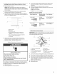


Installing Brackets After Placing Cooktop in Cutout
1. Place cooktop in cutout.
NOTE: Make sure that the front edge of the cooktop is
parallel to the front edge of the countertop. If repositioning is
needed, lift entire cooktop up from cutout to avoid scratching
the countertop,
2. Remove the attachment screws for the selected bracket
locations from the bottom of the burner box,
3. Select bracket mounting holes that will allow the bracket to
extend far enough out from the cooktop for the installation of
21/2'' (6,4 cm) clamping screws
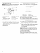
F
A /
E
4=
__ _ .....................D
C
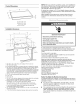
A, Glass cooktop
B, Burner box
C,Attachment screw
D.Clamp bracket (extends far enough beyond
burner box to allow installation of clamping
screws)
E. 2_/2'' (6.4cm) clamping screw (to be installed in
"Attach Cooktop to Countertop')
E Countertop
Attach brackets to burner box bottom with bracket
attachment screws using the bracket mounting holes
selected in Step 3, Securely tighten screws,
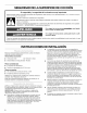
Electrical Shock Hazard
Disconnect power before servicing.
Use 8 gauge copper wire.
Electrically ground cooktop.
Failure to follow these instructions can result in death,
fire, or electrical shock.
This cooktop is manufactured with a frame connected, green or
bare ground wire, Connect the cooktop cable to the junction box
through the UL listed or CSA approved conduit connector.
1. Disconnect power.
2. Remove junction box cover, if present.
3. Connect the flexible cable conduit from the cooktop to the
junction box using a UL listed or CSA approved conduit
connector.
4. Tighten screws on conduit connector if present.
5. Complete installation following instructions for your type of
electrical connection:
4-wire (recommended)
3-wire (if 4-wire is not available)
Electrical Connection Options
If your home has: And you will be
connecting to:
Go to Section:
4-wire direct A fused 4-Wire Cable from
disconnect or Power Supply
circuit breaker
box
(12.7 cm)
3-wire direct A fused 3-Wire Cable from
disconnect or Power Supply
circuit breaker
box
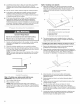
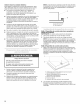
4-Wire Cable from Power Supply
IMPORTANT: Use the 4-wire cable from power supply where local
codes do not permit connecting the frame-ground conductor to
the neutral (white) junction box wire.
A
B
A. Cable from power supply
B. Red wires
C. Green (or bare) ground wires
D. 4-wire cable from cooktop
E. Junction box
F. White wires
G. UL listed wire nut
H. Black wires
L UL listed or CSA approved
conduit connector
1. Connect the 2 black wires together using a UL listed wire nut.
2. Connect the 2 red wires together using a UL listed wire nut.
3. Connect the 2 white wires together using a UL listed wire nut.
4. Connect the green (or bare) ground wire from the cooktop
cable to the green (or bare) ground wire (in the junction box)
using a UL listed wire nut.
5. Replace junction box cover.
6. Reconnect power.